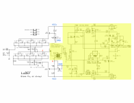
I am going to make LuDEF on the PCB of my own layout. And, of course, I was not smart enough to follow ZM schematics to the very detail - and I did not place a jumper in JP101 (before the pin 2 of autoformer). Now, I read somewhere in this thread that you are supposed to disconnect the jumper before your first set-up when you set 20mV across R106, and put it back after that's done.
Is this essential? Could the 20mV setup process harm the autoformer if it is connected during the process?
In that case, should I (could I) leave the autoformer totaly out of the PCB before I set 20mV across R106?
Is this essential? Could the 20mV setup process harm the autoformer if it is connected during the process?
In that case, should I (could I) leave the autoformer totaly out of the PCB before I set 20mV across R106?
best to first set DC Offset of buffer, then solder xformer in
anyhow - you can set that offset while assembling pcb, you can freely use small bipolar PSU, with everything on pcb while just missing output parts
anyhow - you can set that offset while assembling pcb, you can freely use small bipolar PSU, with everything on pcb while just missing output parts
Just to be clear for the greenhorn (boldish-grey-horn, actually):
ZM, what exactly do you mean by "just missing output parts"? Do you mean jus the output transistors (M101, M103 and J107(LU)), or the entire circuitry as marked in the attached schematics? Would it be ok, if I do not install anything in the yellow zone and apply VCC+ and VCC- on the marked points from the standard +-24V supply? Then set 20mV across R106 and there should be 0V DC between points A and B?
Or, if I put everything on the PCB except just the Edcor. Should I put PCB on the heatsinks while setting DC offset of the buffer, as the output transistors would get hot anyway, even when the xformer is out?
Attachments
meaning - while pcb is still on the bench, so missing both big mosfets and LU, you can apply rails voltage and set buffer fully
after that - solder xformer in, and proceed with pcb mounting on heatsink
after that - solder xformer in, and proceed with pcb mounting on heatsink
A few more questions from me.
Looking for the PSU capacitors now on Mouser. The choice is not as good as it used to be a year or more ago.
I am a simple guy and not a fan of "bigger is better" philosophy, therefore I'm planing for a simple stereo version of LuDEF with a single 400VA 2x19V (potted super-audio grade Toroidy) transformer and would usually go with 2 x 18000uF - 0R1 - 2 x 18000 uF on a standard DIY store PSU board per rail.
But I cannot find 18000uF capacitors what I would be happy with.
Though I do see 22000uF (35VDC, 105C, 24mOhm, 3000hrs) that would suite me.
I know many people go with 22000uF (or even more) and are happy, but are there any drawbacks with that - like bigger inrush current on the start or anything else. Or am I overthinking here, and 22000uF is actually no-brainer?
And another question: what fuse would you reccomend for LuDEF on 230V?
Pa recommends 1.25A for M2X, but 2A for Aleph J. What about LuDEF?
IMO, using only 22.000 uF capacitors for single supply to both channels is going to ruin benefits of potted top quality toroid. You’ll have no or minimal induced 50 Hz EMI at the amplifier output, but there will be enough 100 Hz ripple coming from PS. At 3 A load, first capacitor will have about 1.3 Vpp ripple. Simple RC with 0.1 Ω and 22 mF will reduce ripple by 12 dB or 4 times. That results with 115 mV RMS output ripple. Now, OS has some PSRR and will reduce that but I didn’t measure LuDEF PSRR because there isn’t anything to measure in my version, so I can’t say how much will remain.
It could be a problem with very efficient loudspeakers.
There are very good CDE 47 mF/35 V capacitors available and I would go with that.
As for the fuse, I use 1.6 A fast blowing.
It could be a problem with very efficient loudspeakers.
There are very good CDE 47 mF/35 V capacitors available and I would go with that.
As for the fuse, I use 1.6 A fast blowing.
use caps whichever you want, I'm using what I prefer
regarding fuse, that's easy
Donut VA/ mains V = Fuse A
use first closer standard value, slow blow
if it pops often, use first bigger
NTC soft start is a must
regarding fuse, that's easy
Donut VA/ mains V = Fuse A
use first closer standard value, slow blow
if it pops often, use first bigger
NTC soft start is a must
ZM, why do you need 0R R111 in LuDEF? Are there some circumstances when you need to put some resistance there?
either that, or 3 layer pcb 🙂
couldn't trace it without jumper ........ I mean - I could, but wanted to keep wide power traces on both top and bottom
couldn't trace it without jumper ........ I mean - I could, but wanted to keep wide power traces on both top and bottom
Ok, so on my PCB it's absolutely useless 🙂 As I will have to use exacto-knife and some wire because of the Edcor gremlins anyway, so I'll be able to safely bypass R111 going from Edcor pin 7 straight to C104 🙂 Thanks.
ZEN Mod e ora cosa ne faccio?! :incerto:😱ps:hai bisogno di un dispositivo/presa corrispondente SOT-232
più facile ottenerli da E-Bay - pochi venditori, basta aver cura di sceglierne uno senza neg. zecche
15$ e oltre
il resto è facile: quando ne ottieni uno, ronza e posterò un piccolo schizzo di ciò che è necessario (reg. 7809, interruttore, relè piccolo, alcune prese da 2 mm per sonde DMM)
Attachments
- Home
- Amplifiers
- Pass Labs
- LuDEF