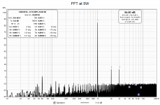
This one is beautiful... I don't care about the total distortion, as in my experience that makes very little difference, but instead look at the very clean curve (or stair step) of the harmonics decay. Nothing out of place, every higher harmonic lower than the previous.
Wonderful!
In a perfect world (well, my world, anyway...) I would adjust until the 'step' between H3 and H4 was a little more smooth.. I.E., lower the total H2 if possible, as that will lower H3 as well, and see if the plots could fit on a horizontal asymptote. It's pretty close as-is, so it may just be gilding the Lilly.
But the entire point of P3 is to fiddle around and try stuff, so might as well try.
Ohh, hey, awesome! That's for the feedback, that's really helpful. I'm glad I'm getting somewhere 🙂
They say the definition of insanity is doing the same thing and expecting different results. I feel like I've been doing the same thing, expecting the same result, but *getting* different results! I'll chock that up to user error. 🙄
For tweaking, the process should be, turn P3 a couple turns in a hopeful direction, zero offset, observe measurement, repeat? That's more ore less what I've been doing. Will continue.
ZM: I will check out those articles, thanks. Does the absolute phase matter, or just the sign (ie, is 87* better or worse than 152*)?
you need to decide with your own ears/brain combo - what you personally prefer
in short - you'll probably find that in Papa's articles ( and why don't you read them all? FW - Articles page) ......... in short :
50% of ppl prefers 2nd dominant, other 50% of ppl prefers 3rd dominant
then each group can be again divided - half is preferring positive phase, other half is preferring negative phase
now, it's just needed that you find out in which of these 4 groups you belong ........
(nice trick Pa told us - when you flip phase of (both) speakers, there is flipped phase of dominant ....... be it 2nd or 3rd)
edit: isn't this hobby wonderful....... sometimes it's just waste spending time on day job .........
Last edited:
Although I‘m still nowhere close to making my first attempts at adjustments (old soul is still on the bench), it is very interesting (although of course confusing 🙂 )reading.
Just a little question out of my non-experienced mind: once the pots are finely tuned in, could those values be „replicated“—that is, the exact same position of the trio would lead to the same offset/bias/thd?
Just a little question out of my non-experienced mind: once the pots are finely tuned in, could those values be „replicated“—that is, the exact same position of the trio would lead to the same offset/bias/thd?
If all parts in the replicated circuit are exact matches to the proto, yes. If not, maybe not. Matching meaning resistors exactly the same, JFET IDSS and pair matching the same, pots and all, and MOSFET Vgs, as well as heatsinking and total temp equilibrium of case. So yes and no, if I understand your question correctly.
enclosed original pic, by 6L6's sayin' in his contribution in latest BAF, written as it was said in proper English
what is posted in quoted post is pure translation to ZMengrish

Dunno about you guys, or the translated party, but I really like ZMEngrish 🙂
Ha! This is what I thought it ought to be. So, theiretically we could make some breakupBoard (or other jigs), containing the preset trimpots (think quasimodo‘s use of a trimpot…If all parts in the replicated circuit are exact matches to the proto, yes. If not, maybe not. Matching meaning resistors exactly the same, JFET IDSS and pair matching the same, pots and all, and MOSFET Vgs, as well as heatsinking and total temp equilibrium of case. So yes and no, if I understand your question correctly.
(But—consider this a brain-fart out of my blooming fantasy…)
Yup.At that point you could wire fixed resistors and bake the setting into the board.
Or prepare various presets…
I was daydreaming about having multiple preset signal paths that could be switched between, so you could select the distortion profile you wanted for a given song/album.
Guitar players already have that ..... 🙂
and even they with time tend to keep number of effects lower ....
once when you have your system good enough, you'll stop worrying about fiddling
and even they with time tend to keep number of effects lower ....
once when you have your system good enough, you'll stop worrying about fiddling
It felt a little bit like https://images.app.goo.gl/UFdg29pq1ofgbaJs9Nice to see you guys again. Been a rough few days during the migration of the site 🙂
I bet the clickrate was the same as for the vfet-lotteries combined…
Nice to see you guys again. Been a rough few days during the migration of the site 🙂
me being furniture, you can just imagine what I'm gone through, during move

Caught up on some sleep time I would think - and got more work done I imagine😎me being furniture, you can just imagine what I'm gone through, during move
Since I’m pretty green with this stuff, I’m trying every combination and setting, because I don’t know how it will sound. So many variables! So many! Especially since I bumped up my heatsinking, so I can experiment with higher bias currents, too.Guitar players already have that ..... 🙂
and even they with time tend to keep number of effects lower ....
once when you have your system good enough, you'll stop worrying about fiddling
I think I’m closing in on what I want though. I’ll post some graphs when I think I have things stable. Then on to my linestage….
Makeover?me being furniture, you can just imagine what I'm gone through, during move
Attachments

I'm pretty happy with my current setup, so I decided to take some proper measurements. All were done into 7 ohms (because that's what I had). Actual output power might be a little higher than stated (1.2W~), but it is consistent.
Most interesting to me was how the distortion profile changed from 1W to 5W. Also that my crosstalk curves upward from 500 Hz.
Most interesting to me was how the distortion profile changed from 1W to 5W. Also that my crosstalk curves upward from 500 Hz.
Attachments
-
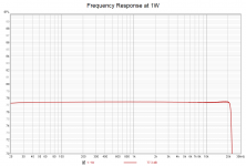 Frequency Response at 1W.png27 KB · Views: 82
 -
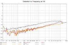 Distortion vs. Frequency at 1W.png32.1 KB · Views: 78
 -
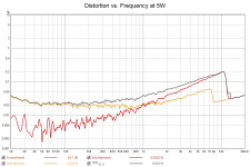 Distortion vs. Frequency at 5W.png28.4 KB · Views: 81
 -
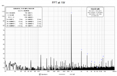 FFT at 1W.png36 KB · Views: 100
 -
 FFT at 5W.png35.6 KB · Views: 81
 -
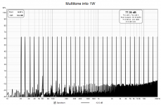 Multitone into 1W.png55.9 KB · Views: 88
 -
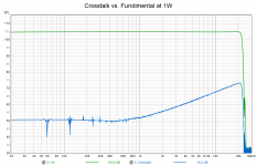 Crosstalk vs. Fundimental at 1W.png18.4 KB · Views: 78
well, even your car is sounding different at 2K and 5K RPM
Are you saying that's when my turbo's kick in? 😛
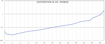
Here's one more, max power before clipping. Measurement was taken into an 8 ohm load, with clipping defined as 1% THD. I beat the spec, reaching just over 36W into 8 ohms!
Incidentally, does anyone know a good way to automatically sweep and measure power vs. distortion? I couldn't find a way to do it in REW, so I plotted these points manually.
Attachments
- Home
- Amplifiers
- Pass Labs
- BA-3 Amplifier illustrated build guide