Hi, I'm new here.
I have a W-King D8 Bluetooth boom box which I'd like to modify with some external speaker output jacks and some buttons to switch the internal speakers on and off, in order to have functionalities which I detail below.
From factory the specs of the boom box are:
-Power Input: DC 5V
-Speaker Output Power: 2 x 25W ( confirmed by Youtube channel Hartdegen review as 12.5W RMS per channel)
-Drivers:
-2 x Woofer, 70mm, 10Ω, 70mm,15W
-2 X Tweeter, 8Ω, 30mm,10W x 2
-Frequency Response: 60Hz - 20kHz
-Battery Type: Li-ion ( 2 x 4000mAh)
-Battery Voltage: 7.4V ( I measured 8v)
-True Wireless Stereo (TWS): Support
-Technology: BT4.2, A2DP, AVRCP, HSP, HFP.
W-King D8 speaker review 50 watts power against JBL xtreme 2 and soundcore Motion plus - YouTube
-The measured resistance at each amplifier output (amp side, speakers disconnected) is 1.2 million ohms, if that is relevant.
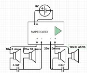
As can be seen from diagram 1, the tweeters have a driver in parallel with them creating a passive high-pass filter I believe (said driver, as I understand it, occupies the same space in the circuit (diagram 1) as the resistor does in typical HPF circuit diagrams, eg. diagram 3). So I used the resistance of this speaker (10 ohms) to figure out what the cut off frequency for signal reaching the tweeter, in the factory design, using fc= 1/(2πRC) = 1/(2π*10*0.0000033) = 4.825KHz.Hope I am on the right track there.
Here are the circuit diagrams, first the speaker diagram from factory, and secondly the diagram of the modification I'd like to make.
Factory:
Diagram 1.
Factory (diagram 1) .JPG
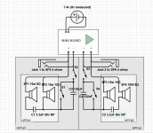
And here with my modifications:
Diagram 2.
Mod (diag. 2).JPG
I have put my doubts and questions in bold. As you can see, I have added into the diagram:
1. Jacks to connect to external speakers.
2. A higher level high pass filter function on each side (HPF #3 and #4), within which you can see that the factory high-pass HPF #1 and #2 are also nested.
3. Switches 1 and 4, which (I hope) allow the built in speakers to be switched into the passive high pass filter configuration which I have added , using capacitors 2 and 3. This could be handy when connecting to external speakers which can better handle the bass part of the audio. For calculating the value of capacitors 2 and 3 in these added HPFs, I have considered the added external speakers (connected through the jacks) to be the 'resistor', and that this external speaker nominally has an impedance of 4 ohms (regarding this I have some questions below).
4. Switches 3 and 4, which allow the built-in speakers to be turned off entirely (eg. when I want only external speakers to be used).
In my modification diagram (factory.jpg), C3 and C4 are 132uF because I'm trying to create a HPFs on each side to block low signal to SP2 and SP3 and that's the value I get for calculating a cut-off value of 300 Hz, according to the formula fc= 1/(2πRC). I use R=4 because I am working on the basis of an ohms ratings for the connected external speaker of 4 ohms. I believe this external speaker becomes a load in parallel with the filtered drivers for the drivers (eg. SP1 and SP), acting like the resistor in the typical HPF filter circuits, like the one I have included.
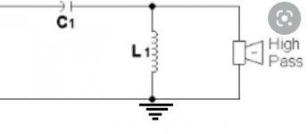
Regarding the HP filter, typical diagrams and explanations are that a resistor is always necessary in parallel with the load (in this case a speaker through which passes filter audio), sometimes with a connection to ground. Eg:
Diagram 3.
highpass with ground (diag.3) .jpg
Am I right in thinking that in fact an extra resistor is not always necessary for a filter like this to work, as the driver itself acts as an inductor and resistance in high pass filters with drivers in circuits like, for example, in this book, which shows the simplest type of HPF?:
Diagram 4.
simplest HPF (diag. 4).JPG
Among other explanations of why a resistor is included in such filter circuits, I have read that 'it is to avoid 'thump' when connecting a load, and to allow a steady state at all times' (+ capacitor capacitor always able to discharge) . However, I am not concerned about an initial 'thump' when connecting a speaker. Also I don't see why this 'steady state', or continually being able to discharge/charge is necessary or advantageous. Actually I see that as a disadvantage potentially, as the amplifier/battery power is being left to drain away through such a resistor completing the circuit (?), even when the external speaker is not connected.
I also see explanations indicating that a resistor helps prevent current leaks to ground, as in the picture above with ground connection. However, as it is a portable speaker in this case, there is no ground connection, so why would a resistor be necessary there to prevent current leakage to ground?
Another explanation I've read is that "if you want to predict the filter's performance you need to know how much resistance is in series with the signal. A theoretical source with zero impedance will not be affected by the capacitor. If the signal is coming from something which has significant output impedance, then an additional resistor may not be needed."
Regarding that explanation, I DO know the resistance which is in series with the signal, (4ohms - not a theoretical 0 ohms), so why the need for an additional resistor in parallel with it?
I also have the following questions:
I figure that the addition of capacitors C3 and C4 will continuously affect the cutoff frequency of HPF#1 and #2 (factory installed HPFs), which filter the signal to speakers 1 and 4, because the resistance of the parallel 'resistor' each sees will vary. I figure this because, taking HPF#3 for example, the 'resistor' it sees when speaker 5 is connected and switch 1 is open will no longer be just speaker 2, but the combined resistance of speaker 2, capacitor 3, and speaker 5 all in parallel. Thus the 'resistor' of HPF#1 will vary continuously as the frequency of the signal into capacitor 3 changes (the changing audio signal). Perhaps it will also be affected slightly by varying amounts of back EMF produced by speakers 2 and 5? How much is all this likely to affect the filtered output of speaker 1 in this scenario?
EMF: https://www.edn.com/loudspeaker-oper...voltage-drive/
https://mynewmicrophone.com/the-comp...-8%CF%89-more/
Will typical 3.5 mm audio jacks be able to handle the current flowing through speakers 5 and 6? I also have phono plugs, but there isn't much space to work with inside the enclosure part where the electronics are, so I'd like to go with smallest components if possible. I'm also not sure what rating the switches would have to meet. When S1 and S2 are closed and SP5 is connected, I have calculated that theoretically the peak current through switch 1, switch 2, and jack 1 (when all the signal is above the cut-off frequencies), would be I=V/R = 7.4v / (1/((1/8Ω)+(1/10Ω)+(1/4Ω)) = 3.515a. This is ignoring any back EMF induced in the speakers (if indeed this is a real issue).
I notice the rating for switches is often higher when used in 110 Volts circuits than when the same switch is used in a 240v circuit. Is this something to do with the rating being partly determined by the power (P=IV), not just the current flow through the component?
Am I right in thinking capacitor 3 will do nothing (remain infinite resistance) when switch 1 is closed?
I have a W-King D8 Bluetooth boom box which I'd like to modify with some external speaker output jacks and some buttons to switch the internal speakers on and off, in order to have functionalities which I detail below.
From factory the specs of the boom box are:
-Power Input: DC 5V
-Speaker Output Power: 2 x 25W ( confirmed by Youtube channel Hartdegen review as 12.5W RMS per channel)
-Drivers:
-2 x Woofer, 70mm, 10Ω, 70mm,15W
-2 X Tweeter, 8Ω, 30mm,10W x 2
-Frequency Response: 60Hz - 20kHz
-Battery Type: Li-ion ( 2 x 4000mAh)
-Battery Voltage: 7.4V ( I measured 8v)
-True Wireless Stereo (TWS): Support
-Technology: BT4.2, A2DP, AVRCP, HSP, HFP.
W-King D8 speaker review 50 watts power against JBL xtreme 2 and soundcore Motion plus - YouTube
-The measured resistance at each amplifier output (amp side, speakers disconnected) is 1.2 million ohms, if that is relevant.
As can be seen from diagram 1, the tweeters have a driver in parallel with them creating a passive high-pass filter I believe (said driver, as I understand it, occupies the same space in the circuit (diagram 1) as the resistor does in typical HPF circuit diagrams, eg. diagram 3). So I used the resistance of this speaker (10 ohms) to figure out what the cut off frequency for signal reaching the tweeter, in the factory design, using fc= 1/(2πRC) = 1/(2π*10*0.0000033) = 4.825KHz.Hope I am on the right track there.
Here are the circuit diagrams, first the speaker diagram from factory, and secondly the diagram of the modification I'd like to make.
Factory:
Diagram 1.
Factory (diagram 1) .JPG
And here with my modifications:
Diagram 2.
Mod (diag. 2).JPG
I have put my doubts and questions in bold. As you can see, I have added into the diagram:
1. Jacks to connect to external speakers.
2. A higher level high pass filter function on each side (HPF #3 and #4), within which you can see that the factory high-pass HPF #1 and #2 are also nested.
3. Switches 1 and 4, which (I hope) allow the built in speakers to be switched into the passive high pass filter configuration which I have added , using capacitors 2 and 3. This could be handy when connecting to external speakers which can better handle the bass part of the audio. For calculating the value of capacitors 2 and 3 in these added HPFs, I have considered the added external speakers (connected through the jacks) to be the 'resistor', and that this external speaker nominally has an impedance of 4 ohms (regarding this I have some questions below).
4. Switches 3 and 4, which allow the built-in speakers to be turned off entirely (eg. when I want only external speakers to be used).
In my modification diagram (factory.jpg), C3 and C4 are 132uF because I'm trying to create a HPFs on each side to block low signal to SP2 and SP3 and that's the value I get for calculating a cut-off value of 300 Hz, according to the formula fc= 1/(2πRC). I use R=4 because I am working on the basis of an ohms ratings for the connected external speaker of 4 ohms. I believe this external speaker becomes a load in parallel with the filtered drivers for the drivers (eg. SP1 and SP), acting like the resistor in the typical HPF filter circuits, like the one I have included.
Regarding the HP filter, typical diagrams and explanations are that a resistor is always necessary in parallel with the load (in this case a speaker through which passes filter audio), sometimes with a connection to ground. Eg:
Diagram 3.
highpass with ground (diag.3) .jpg
Am I right in thinking that in fact an extra resistor is not always necessary for a filter like this to work, as the driver itself acts as an inductor and resistance in high pass filters with drivers in circuits like, for example, in this book, which shows the simplest type of HPF?:
Diagram 4.
simplest HPF (diag. 4).JPG
Among other explanations of why a resistor is included in such filter circuits, I have read that 'it is to avoid 'thump' when connecting a load, and to allow a steady state at all times' (+ capacitor capacitor always able to discharge) . However, I am not concerned about an initial 'thump' when connecting a speaker. Also I don't see why this 'steady state', or continually being able to discharge/charge is necessary or advantageous. Actually I see that as a disadvantage potentially, as the amplifier/battery power is being left to drain away through such a resistor completing the circuit (?), even when the external speaker is not connected.
I also see explanations indicating that a resistor helps prevent current leaks to ground, as in the picture above with ground connection. However, as it is a portable speaker in this case, there is no ground connection, so why would a resistor be necessary there to prevent current leakage to ground?
Another explanation I've read is that "if you want to predict the filter's performance you need to know how much resistance is in series with the signal. A theoretical source with zero impedance will not be affected by the capacitor. If the signal is coming from something which has significant output impedance, then an additional resistor may not be needed."
Regarding that explanation, I DO know the resistance which is in series with the signal, (4ohms - not a theoretical 0 ohms), so why the need for an additional resistor in parallel with it?
I also have the following questions:
I figure that the addition of capacitors C3 and C4 will continuously affect the cutoff frequency of HPF#1 and #2 (factory installed HPFs), which filter the signal to speakers 1 and 4, because the resistance of the parallel 'resistor' each sees will vary. I figure this because, taking HPF#3 for example, the 'resistor' it sees when speaker 5 is connected and switch 1 is open will no longer be just speaker 2, but the combined resistance of speaker 2, capacitor 3, and speaker 5 all in parallel. Thus the 'resistor' of HPF#1 will vary continuously as the frequency of the signal into capacitor 3 changes (the changing audio signal). Perhaps it will also be affected slightly by varying amounts of back EMF produced by speakers 2 and 5? How much is all this likely to affect the filtered output of speaker 1 in this scenario?
EMF: https://www.edn.com/loudspeaker-oper...voltage-drive/
https://mynewmicrophone.com/the-comp...-8%CF%89-more/
Will typical 3.5 mm audio jacks be able to handle the current flowing through speakers 5 and 6? I also have phono plugs, but there isn't much space to work with inside the enclosure part where the electronics are, so I'd like to go with smallest components if possible. I'm also not sure what rating the switches would have to meet. When S1 and S2 are closed and SP5 is connected, I have calculated that theoretically the peak current through switch 1, switch 2, and jack 1 (when all the signal is above the cut-off frequencies), would be I=V/R = 7.4v / (1/((1/8Ω)+(1/10Ω)+(1/4Ω)) = 3.515a. This is ignoring any back EMF induced in the speakers (if indeed this is a real issue).
I notice the rating for switches is often higher when used in 110 Volts circuits than when the same switch is used in a 240v circuit. Is this something to do with the rating being partly determined by the power (P=IV), not just the current flow through the component?
Am I right in thinking capacitor 3 will do nothing (remain infinite resistance) when switch 1 is closed?
Attachments
-
 Factory (diagram 1) .JPG90.5 KB · Views: 250
 -
 Mod (diag. 2).JPG98.8 KB · Views: 285
 -
 highpass with ground (diag.3) .jpg14.5 KB · Views: 224
 -
 simplest HPF (diag. 4).JPG54 KB · Views: 264
 -
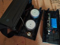
 IMG_20211116_144108.jpg965.9 KB · Views: 177
 -
 IMG_20211129_131500.jpg197.1 KB · Views: 125
 -
 Jacks I plan to use (side).jpg170.9 KB · Views: 131
 -
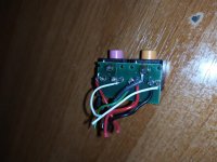 Jacks I plan to use (top).jpg649.3 KB · Views: 104
Last edited:
Welcome to the forum.Hi, I'm new here.
Let's start here: "As can be seen from diagram 1, the tweeters have a resistor in parallel creating a passive high-pass filter I believe."
This should read "As can be seen from diagram 1, the tweeters have a 3.3 uF capacitor in series, creating a high-pass filter."
Perhaps this may help you redraft/simplify your post.
P.S. Is it a prime requirement that both the internal and external speakers are able to play at the same time as well as separately?
Welcome to the forum.
Let's start here: "As can be seen from diagram 1, the tweeters have a resistor in parallel creating a passive high-pass filter I believe."
This should read "As can be seen from diagram 1, the tweeters have a 3.3 uF capacitor in series, creating a high-pass filter."
HI Galu,
By 'resistor', in that diagram I am referring to the 20w speaker driver, not the capacitor. I refer to it as a resistor because it fills the place occupied by a resistor in the typical HPF circuit diagrams one can find. I was referring more to its function than type of component, trying to make sense of its role in the circuit, based on the stock circuit diagrams you get for HPFs. Just like in these circuits, eg. diagram 3 above, the load ('resistor'/speaker in my analogy) is in parallel with the speaker which is receiving the filtered signal. I hope you get what I mean.
I have since learned that a resistor is not always necessary in HPFs, like in diagram 4 for example. That was one of the questions in my post. I would appreciate any clarification of that still though.
Welcome to the forum.
Let's start here: "As can be seen from diagram 1, the tweeters have a resistor in parallel creating a passive high-pass filter I believe."
This should read "As can be seen from diagram 1, the tweeters have a 3.3 uF capacitor in series, creating a high-pass filter."
P.S. Is it a prime requirement that both the internal and external speakers are able to play at the same time as well as separately?
If it is feasible, yes, I would like to have the option of internal speakers playing while external speakers are also playing, with low signal filtered out from the internal speakers (leaving the low frequency signal to be handled by larger external speakers.) That's my idea behind what I have come up with and labelled as HPF#3 and HPF#4 in diagram 2. If it is too complicated, or the performace of HPF#3 and #4 would be continuously affected by SP5/SP6 making a crossover with a steady crossover cutoff impossible, or a bad idea for some other reason, I will make do with just the option of either external speakers or internal in use at any one time.
I have edited the thread starter to make it a bit clearer why I referred to a speaker as a resistor there.
Keep in mind that the amplifier is probably class D and can be damaged if for some reason (internal speaker off, no external speaker) no speaker is connected. Same may happen if you connect speakers in parallel and the resulting impedance is too low for the amp. Or the protection circuit shuts the amp off.
Last edited:
Also bear in mind that the the electronics in your small portable device will employ digital signal processing to boost the bass delivered by its small bass drivers.
If the same processed signal is applied to larger external speakers, the result is likely to be an overly bass heavy and bloated sound.
If the same processed signal is applied to larger external speakers, the result is likely to be an overly bass heavy and bloated sound.
Your equation for calculating the HPF cut off frequency, f, is basically correct. The accepted form of the equation is:
Xc = 1 / (2 * pi * f * C)
Where Xc is the reactance of the capacitor, which must match the nominal impedance of the tweeter.
So, as I think you understand, the "resistor" of which you speak is simply the nominal impedance of the tweeter.
Xc = 1 / (2 * pi * f * C)
Where Xc is the reactance of the capacitor, which must match the nominal impedance of the tweeter.
So, as I think you understand, the "resistor" of which you speak is simply the nominal impedance of the tweeter.
Last edited:
Keep in mind that the amplifier is probably class D and can be damaged if for some reason (internal speaker off, no external speaker) no speaker is connected. Same may happen if you connect speakers in parallel and the resulting impedance is too low for the amp. Or the protection circuit shuts the amp off.
OK that's interesting thanks.
Regarding whether this might happen when speakers are connected as per diagram 2, this is what I am looking for help here in calculating. Any assistance appreciated, particularly calculating varying resistances due to back EMF/inductance of the drivers themselves, etc..
Also bear in mind that the the electronics in your small portable device will employ digital signal processing to boost the bass delivered by its small bass drivers.
If the same processed signal is applied to larger external speakers, the result is likely to be an overly bass heavy and bloated sound.
Thanks I have considered that. THe boom box has two 'EQ' modes. If more is required I will sort that out after it leaves the boom box. Before putting it back together I'm going to have a listen to the output from the amp directly on hifi speakers. See what the EQ is like.
Last edited:
So, as I think you understand, the "resistor" of which you speak is simply the nominal impedance of the tweeter.
Exactly. I used this nominal impedance as the 'resistor' value in the HPF capacitor calculation formula.
What I am not sure about regarding this, and as I asked about in the OP, is how this resistance value might change as signal goes through the driver. For example, on the left stereo side, the resistance offered by S5 will vary due to back EMF/inductance induced by its coils. From the theory I have read, I figure the cutoff frequency of signal reaching S2 will vary as a result of that varying resistance, given the cutoff frequency in a filter is determined by Xc = 1 / (2 * pi * f * C).
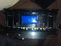
According to the code on the circuit board, the amplifier is this:
TPA3118D2 data sheet, product information and support | TI.com
TPA3118D2 data sheet, product information and support | TI.com
According to the code on the circuit board, the amplifier is this:
TPA3118D2 data sheet, product information and support | TI.com
TPA3118D2 data sheet, product information and support | TI.com
The impedance of the tweeter may increase slightly with frequency, but not enough to upset your simple series capacitor filter.
I suppose that, technically, Xc should equal the impedance of the tweeter at the desired crossover frequency, but for such a simple filter the figure for the nominal impedance will suffice.
The capacitor value can be allowed to change by, say, around 20% without making any appreciable effect on the tweeter output.
P.S. Impedance (the opposition to alternating current) includes the effect of inductance and back emf, so there is no need to regard those as separate entities when designing your high pass filter.
Regarding your switching arrangements, again inductance and back emf are not a consideration.
As stv has pointed out, because your amplifier is Class D, any switching arrangement must ensure that under no circumstances can the amplifier run with no load.
Your proposed method of switching in Diagram 2 will not ensure the above.
As stv has pointed out, because your amplifier is Class D, any switching arrangement must ensure that under no circumstances can the amplifier run with no load.
Your proposed method of switching in Diagram 2 will not ensure the above.
As stv has pointed out, because your amplifier is Class D, any switching arrangement must ensure that under no circumstances can the amplifier run with no load.
Your proposed method of switching in Diagram 2 will not ensure the above.
Indeed. In the specs sheet for the amplifier I have just found it says the minimum load is 4 ohms. Apart from unloaded scenarios, this could be a problem for my circuit I think, based on the current calculation below.
In my diagram (2), If speaker 5 is connected and S1 is open AND S2 closed, the amplifier outputs will see SP1, SP2, and SP5 in parallel. Thus the minimum resistance it can see will be 1/((1/8+(1/10)+(1/4)) which equals 2.10 ohms. Maximum current (assuming no filter is placed on SP5) will therefore be, according to my calculations, 7.4/2.10 = 3.515 a. This also ignores potential resistance from C1 and C3.
Can someone confirm if my calculations there are correct?
If they are, I think I may have to abandon the idea of having external speakers in parallel with the internal ones because the resistance seen by the amplifier comes out lower than the minimum 4 ohms spec of the amp.
I have a couple of audio jacks which are the switching type, i.e they switch between two sets of contacts on the back depending on whether a jack is plugged in or not. I could use this to switch between one circuit where the external speakers are connected and a second circuit where just the internal ones are. The question there is whether jacks of that type can handle the current that might flow out of an amp like this. Anyone know?
Your calculations need to be adjusted
The impedance of the internal speaker combination may be taken as the impedance of the woofer which is 10 ohm. Put a 4 ohm external speaker load in parallel and the resultant load is around 2.9 ohm.
Also, the current to the speaker load is a variable quantity which will average out at considerably less than your calculation of supply voltage divided by speaker impedance. Consequently, any switching speaker jack should be adequate to the task of switching between internal and external speakers.
I once put switched jacks on my radio/cassette player so I could connect external speakers while disconnecting the internal ones.
I always made sure the 'boom box' was switched off when plugging in the external speakers, in order to avoid possible amplifier damage.
I suggest you forget about your calculations and simply concentrate on how to wire those switching jacks. 🙂
How can this be 10 ohms? In the above why have you ignored the the tweeter (SP1) which is parallel with the woofer (SP2)? The resistance of two resistors in parallel is calculated using 1/(1/R1)+(1/R2).Your calculations need to be adjusted
The impedance of the internal speaker combination may be taken as the impedance of the woofer which is 10 ohm.
According to which, 1/((1/8+)(1/10)) which equals 2.10 ohms.
As I said before, this ignores any varying impedance due to induction, which you have said will be negligible, so I have ignored it.
On another forum I was told the resistance of the internal speakers would be 8ohms! No calculations shown. Totally confusing and doesn't seem to correspond with ohms law at all.
The HPF capacitor C1 will also add resistance by blocking signal below its cut-off, but its resistance will still not be infinite. Could you show me your calculations for how you arrived at 10 ohms for the resistance of the internal speakers on each side?
Thanks yes I was calculating the max current draw at any given moment there, assuming all signal gets through all filters. Worst case scenario, and highly unlikely to be anything more than very transient sounds (of high frequency), right?Also, the current to the speaker load is a variable quantity which will average out at considerably less than your calculation of supply voltage divided by speaker impedance.
Last edited:
The filter ensures that the tweeter is not working in parallel with the woofer at the mid/bass frequencies, so a parallel to the woofer calculation is wrong.
So how does one calculate it? The crossover cut-off looks to be 4.825KHz using fc= 1/(2πRC) = 1/(2π*10*0.0000033) = 4.825KHz. So we can assume the tweeter only gets to handle signal mainly above 4.8 KHz, but these are small woofers (3 inches) and they will also be handling some of the signal above that cut-off frequency, so it can't just be as simple as 'one or the other', so to speak, handling signal at any one time, so they must be in parallel to some degree.
I want to learn how a little about how this stuff is calculated. I already knew about ohms law and some circuit basics.
I want to learn how a little about how this stuff is calculated. I already knew about ohms law and some circuit basics.
Last edited:
The impedance rating of a loudpeaker takes into account the resistance of the speaker's voice coil as well as the back EMFs produced by its inductance....this ignores any varying impedance due to induction...
The resistance remains the same at all frequencies, but the inductive effects vary with frequency.
A speaker with an impedance of 8 ohm at a particular frequency could have a resistance of 6 ohm - the other 2 ohm being due to the inductive nature of the voice coil.
(Impedance also includes opposition due to capacitive effects in the voice coil, but best we gloss over that for now!)
- Home
- Loudspeakers
- Multi-Way
- Begginer help with boom box modification.