If we look at the 8 ohm tweeter, then at the crossover frequency it is in series with a capacitor with an Xc of 8 ohm. The total impedance of the tweeter circuit is therefore 16 ohm at this frequency....but these are small woofers (3 inches) and they will also be handling some of the signal above that cut-off frequency, so it can't just be as simple as 'one or the other', so to speak, handling signal at any one time, so they must be in parallel to some degree.
Put that in parallel with the 10 ohm woofer and you get an effective impedance of PRODUCT / SUM = (16 x 10) / (16 + 10) = 160 / 26 = 6.2 ohm, but only at the crossover frequency (and falling to no less than 4.4 ohm as Xc tends to zero at the highest frequencies where there is very little signal current involved anyway).
However, it is the impedance at the mid/bass frequencies which is important because that is where the majority of the music power resides - and that basically equals the impedance of the woofer i.e. 10 ohm.
It is too easy to overthink this. If you consider that the impedance of a loudspeaker varies widely with frequency you will realise that a few ohm here or here make no difference.
All that is necessary is that the impedance remains above 4 ohm over the majority of the frequency range in order to avoid damage to your amplifier.
Attachments
The formula I used in post #1 was fc= 1/(2πRC). This is the formula I used for calculating the crossover frequency. Are you saying that the formula you have there (Xc = 1 / (2 * pi * f * C) is just a transposition of fc= 1/(2πRC)?Your equation for calculating the HPF cut off frequency, f, is basically correct. The accepted form of the equation is:
Xc = 1 / (2 * pi * f * C)
Where Xc is the reactance of the capacitor, which must match the nominal impedance of the tweeter.
If so, does the 'R' in fc= 1/(2πRC) represent nothing more than the capacitvie reactance (Xc) in Xc = 1 / (2 * pi * f * C)?
If we look at the 8 ohm tweeter, then at the crossover frequency it is in series with a capacitor with an Xc of 8 ohm. The total impedance of the tweeter circuit is therefore 16 ohm at this frequency.
Could you show me how you got a value of 8 ohms for the capacitive reactance of the capacitor in parallel with the tweeter?
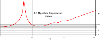
Thanks for that image of the 8ohm speaker impedance curve. So, basically the impedance ratings you see with speakers are the minimum impedance they offer across the normal frequency range?
Last edited:
The formula is Xc = 1/(2πfC). There is no R in this formula. Your transposition is correct if you replace R with Xc.
The opposition of a capacitor to the flow of alternating current is called capacitive reactance (Xc).
Although the mechanism of capacitive reactance is different to that of resistance, capacitive reactance is also measured in ohms.
The formula Xc = 1/(2πfC) allows you to calculate the capacitive reactance of a particular capacitor (C) at a particular crossover frequency (f).
When putting a capacitor in series (not in parallel as you have said) with a tweeter, the object is to choose a capacitor whose capacitive reactance (Xc) equals the rated (nominal) impedance (Z) of the tweeter at the desired crossover frequency (f). Now you start playing with the formula - insert the desired crossover frequency and try different values of C until Xc equals the rated (nominal) impedance of the tweeter.
Regarding the speaker impedance curve:
Impedance (Z) is the total opposition of a loudspeaker to the flow of alternating current. Impedance combines the effects of resistance, capacitive reactance and inductive reactance. As you saw in the graph I supplied, impedance varies with frequency.
If you measure the resistance (R) of your speaker's voice coil with an ohmmeter, you will find that it is about 75% of the rated (nominal) impedance (Z) of the driver. An 8 ohm driver, for instance will usually have a resistance of about 6 ohms. This tells you that impedance is something more than simple resistance.
I suggest you buy an elementary book on speaker building. My recomendation is "Building Speaker Enclosures" by David Weems.
So, basically the impedance ratings you see with speakers are the minimum impedance they offer across the normal frequency range?
Very often, the impedance rating given by the manufacturer is the impedance at a certain frequency in the operating range of the speaker.
For example, the rated impedance of a mid/woofer could be its impedance at 400 Hz. https://education.lenardaudio.com/en/05_speakers_3.html
P.S. Obviously, if you know the capacitor value and the required capacitive reactance (equal to the rated impedance of the tweeter), then you can use the transposed formula fc = 1/(2πXcC) to calculate the crossover frequency.
So it looks like I'm going to add the two 3.5mm jack sockets (jack 1 and 2 in diagram 2) and have it so either the external speakers or internal speakers are in use at any one time, never both, but always one or the other. I have a couple of 3.5mm jack TRS sockets with 5 pins which will allow switching automatically between the internal speakers and any connected external ones simply by plugging in a 3.5mm jack into each socket.
I'm concerned about interference from these speaker output jack sockets. The most convenient place to put the jack sockets are epoxed right onto the amp board and then drill a couple of small round holes in the casing for them (it's not a sealed section of the box). At this location they will be 1cm (10mm) from the line level aux input, and right up against the amplifier board.
Could the signal carried through those output sockets create sufficient electromagnetic interference to possibly interfere with the signal on the amplifier board, or the signal coming in through the aux inputs 1cm away?
Any magnetic field associated with the current flowing in the speaker output sockets will be much too weak to affect the signals present on the amp board or coming in at the aux inputs.
Perhaps you are thinking about radio frequency (RF) interference, which would not be radiated by your speaker sockets.
Perhaps you are thinking about radio frequency (RF) interference, which would not be radiated by your speaker sockets.
No, I was indeed thinking of electro-magnetic interference. I have read in some forums that crosstalk between speaker wires can be a potential issue above certain power levels (eg..'hundreds of watts') if the wires are right next to each other. THe power out of these outputs would be much lower (25 watts peak), but given the much greater sensitivity at an aux input or the pre-amplified signal on the board after the bluetooth signal is received, I wondered if that signal being so close to the board and line level input could be an issue.
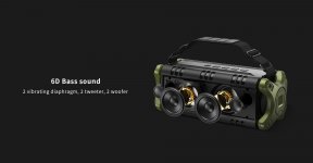
On this photo, it would be the other side of the board, from where the USB socket is.
On this photo, it would be the other side of the board, from where the USB socket is.
Attachments

Last edited:
I have a W-King D8 Bluetooth boom box which I'd like to modify with some external speaker output jacks...
I thought it would be nice to attach an image of your "boom box". 😎
Regarding your mention of "crosstalk", I believe this would only be an issue with long lengths of speaker cabling when carrying large currents.
You may be surprised to learn that your average listening level is likely to be at around only a couple of watts!
Attachments
I'll just add that there will be no long lengths of speaker wiring inside your boombox so what you're reading about potential cross talk is not applicable.
There will basically be just the speaker output sockets themselves, and there will be little chance of electromagnetic coupling between them and the rest of the circuitry within the boombox.
I believe I said earlier that you were overthinking things for this simple project. 🙂
There will basically be just the speaker output sockets themselves, and there will be little chance of electromagnetic coupling between them and the rest of the circuitry within the boombox.
I believe I said earlier that you were overthinking things for this simple project. 🙂
WOuld it make any noticeable difference to sound quality or frequency response if I put a 4 ohm resistor right at the output of the amplifer, one on each side, for the purposes of ensuring that there is always a load for the amp, or perhaps for raising the impedance to ensure it is always above 4 ohms minimum rating for this amp, thus allowing external speakers in parallel without fear of overload?
Just thinking again that the way I use this boom box it would be really handy to have the option of the external and internal speakers in parallel becasue we sometimes just bring the boom box and one bigger speaker to handle the bass.
Obviously I'm suffering from beginners uncertainty to a degree but I'm not sure what you mean by overthinking the project. I'll only get one shot to get it right I think, becasue it's a bitch opening the box. I would like to know the applicable formulas so I can understand what's going on at a deeper level, and perhaps do different kinds of calculations myself in the future. That capacitive reactance one in your posts above was an interesting one.
Yeah that's the boom box in the photo there. Solid unit. Good value as well.
Last edited:
You are describing two different scenarios:
e.g. In the case of adding a 4 ohm resistor in series with the combined 2.9 ohm speaker load of your scenario, you will lose more than half of the amplifier power in the resistor.
In addition, adding the resistor is, indeed, likely to affect the response of the connected loudspeakers.
I'm not even going to go anywhere near puzzling out the switching arrangement you would need!
- To ensure there is always a load on the amp, the 4 ohm resistor would have to be switched in parallel with the amp output when no speaker is connected.
- To raise the impedance when connecting an external speaker in parallel with the internal speaker, you would have to switch a suitable resistor in series with the parallel combination of internal and external speaker.
e.g. In the case of adding a 4 ohm resistor in series with the combined 2.9 ohm speaker load of your scenario, you will lose more than half of the amplifier power in the resistor.
In addition, adding the resistor is, indeed, likely to affect the response of the connected loudspeakers.
I'm not even going to go anywhere near puzzling out the switching arrangement you would need!
- Home
- Loudspeakers
- Multi-Way
- Begginer help with boom box modification.