At low power; normally yes, but IME, batches of drivers tended to not be close enough for one reason or another, so one reason I quickly shy'd away from continuing line array experimentation and judging from some folk's measurements it's still can be a problem with some brands.
JG's original line array wide range? drivers definitely had some random bottoming issues due to power sharing issues when trying to keep up with the Babb Lorelei's 1" Xmax.
JG's original line array wide range? drivers definitely had some random bottoming issues due to power sharing issues when trying to keep up with the Babb Lorelei's 1" Xmax.
I have measured both voice coil DCR and inductance. Then I put together the drivers in groups of three matched to within one percent. These are the series groups. Then I'll put those three triplets in parallel, to get 8 Ohms. So the impedance remains the same as a single driver, the total sensitivity of the array is about 9.5dB higher than a single driver(86dB), and there is no shading (that I can determine).
By crossing over to the (~92dB)treble array at the baffle-step frequency, I hope to get an acceptable compensation in the L.F. response for the narrow baffle (95.5 - 92 = 3.5dB higher below baffle step, using a first order crossover centered on the baffle-step frequency).
Please correct me if I've missed something.
Thanks
Last edited:
Please stop considering any plan that incorporates First-Order filters! You're already studying/analyzing (with maths -- forgive me for mentioning 😉) solutions that ReQUIRE a more sophisticated crossover!
There certainly are design situations in which a First-Order crossover is well suited. This is not one of them.
Cheers
There certainly are design situations in which a First-Order crossover is well suited. This is not one of them.
Cheers

Thanks for the warning.
What do you recommend for a simple 700hz crossover between two identical 3" full range drivers with relatively extended frequency response from 160-10,000hz?
Again this is the baffle-step frequency of my 6" wide towers.
Thanks in advance for contributing.
Last edited:
😕
Dear GM:
I'm sorry...
Could you PLEASE send me "that" link for (proper) crossover design?
From my attempts at the links you previously posted, all that I saw were for baffle-step correction and ported box calculation. I couldn't find a link for crossover design in the lot! (I'm trying hard to learn alot in a short time)
Thanks sincerely,
-Charles
Hmm, thought you were only interested in the BSC calculation since you referenced it to the baffle width, which gives the F6 point, pass-band frequencies; one does not normally put a proper XO in this sloping BW, only well before or after it.
If wanting an XO to shelve down one of two sets of three drivers to create the BSC F6 slope, then admittingly guessing, seems like it would need a cascaded multiple slope order to mimic 1st order over the slope's rather narrow BW, so personally would have to learn to use one of the XO designers as it would indeed 'ReQUIRE a more sophisticated crossover!'
Makes me the sorry one this time. 🙁
'If wanting an XO to shelve down one of two sets of three drivers to create the BSC F6 slope, then admittingly guessing, seems like it would need a cascaded multiple slope order to mimic 1st order over the slope's rather narrow BW, so personally would have to learn to use one of the XO designers as it would indeed 'ReQUIRE a more sophisticated crossover!'
I've AcQUIREd a copy of X-Sim, but don't have FRD/ZMA data files for my Tang Band W3-665sc drivers (on close inspection, they look like essentially the same driver as the TB W3-593SF, but without the silver color). Sadly, I can't find the files on PartsExpress' website. 😕
Any referal links or data would be appreciated.
Thanks
-Charles
What do you recommend for a simple 700hz crossover between two identical 3" full range drivers with relatively extended frequency response from 160-10,000hz?
1st order.
dave
Chasmo, if you want the simplest answer, double it. If you want to know the inductor value with BSC, take the normal value for crossing at that frequency, then double it to take care of BSC too.
(Varies with frequency. Optimum when the cross is a little higher than the baffle step. Terms and conditions available on the web site for new and existing customers. Fees and charges may apply.)
Passive / bass unit / variable cross-over
(Varies with frequency. Optimum when the cross is a little higher than the baffle step. Terms and conditions available on the web site for new and existing customers. Fees and charges may apply.)
Passive / bass unit / variable cross-over
Ok, so instead of using a 1.5mH choke for a 750Hz low pass (then adding a separate BSC filter), I'll be using a 3mH choke (if no resistor across the choke, it will be a 375Hz low pass?). Is that what I need?...if you want the simplest answer, double it. If you want to know the inductor value with BSC, take the normal value for crossing at that frequency, then double it to take care of BSC too...
Also, I'll be using a series RC Zobel of 7ohms & 2uF (how critical are the values/toleranceso?) wired from "+" to "-" woofer terminals. I assume this will help the series choke to do its job(s).
Thanks
Last edited:
Yes, the series RC will help. The values don't need to be exact. I expect you'll want to make adjustments after you do it, you just need something to get you close enough at the start.
If you have the frequency in the middle of the baffle step, and the crossover frequency I might be able to be more specific.
If you have the frequency in the middle of the baffle step, and the crossover frequency I might be able to be more specific.
If you have the frequency in the middle of the baffle step, and the crossover frequency I might be able to be more specific.
About that:
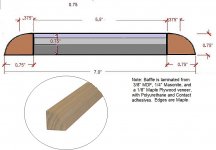
I realized that because I had centered the drivers on the 6" baffles, side edge diffraction would be reinforced. So, I cut 1/2" off one (inside) edge of each baffle, which now makes the width 5.5". To restore the width and further reduce edge diffraction, I found some 3/4" hardwood quarter round stock in maple (like my baffle veneer). Unfortunately (I've realized), I'm not really certain of the exact baffle width now, due to the curve. I don't want to replace the baffles, because I put a lot of effort into laminating them (see image). They are very inert for wood baffles.
Looking at the cross-section, I see that it is mostly flat 6" across, with a pretty rapid radius to the full 7" with at the rear surface. I'm guessing somewhere between 6" and 6.5", as there is no longer a sharp edge.

Would you say the effective baffle width is 6" or closer to 7" for sound waves in the midrange? I will customize the crossover to the appropriate frequency.
Thanks.
Attachments
Last edited:
I see. Theory suggests the baffle step will be roughly 700Hz, but when it's narrow and at the same time tall, that can go down maybe an octave. Which is probably fine for your roughly 700Hz cross to make it look like a first order filter after BSC (if that's what you want).
By the way, if it were me I'd stop cutting bits off the baffle.
By the way, if it were me I'd stop cutting bits off the baffle.
"...By the way, if it were me I'd stop cutting bits off the baffle..."

'Give ' em an inch!'
😉
But seriously- Wouldn't you take an improvement in edge diffraction if you could?
Thanks for all the help, tho'. (Lots of work to do now).
-Charles
'Give ' em an inch!'
😉
But seriously- Wouldn't you take an improvement in edge diffraction if you could?
Thanks for all the help, tho'. (Lots of work to do now).
-Charles
Lol 🙂
Anyway you're not reducing edge diffraction, you're simply rearranging it. Plus making it smaller pushes it up in frequency to where it can be more audible. If I can't put a source in the middle of its surrounding structure then I haven't designed it well enough for the job. In its simplest guise this means roundovers.
Sometimes this isn't practical, so it's just a suggestion.
Yeah, a 1.5" [total] diameter = ~13543/pi/1.5 = ~2,874 Hz, so any lower will increasingly become omni, i.e. can't 'feel' it.
Thanks! 🙂Yeah, a 1.5" [total] diameter = ~13543/pi/1.5 = ~2,874 Hz, so any lower will increasingly become omni, i.e. can't 'feel' it.
My mid drivers will be crossing over below 3kHz, so at least my tweeter will have asymmetrical placement AND a smoother baffle edge (It's a 3.5" planar, so the dispersion is pretty narrow in the vertical). And it's relatively flush-mounted too (BG Neo-3 style tweeter doesn't have a flat faceplate).
Thanks to everyone who has contributed.
-Charles
- Home
- Loudspeakers
- Multi-Way
- Help Converting Line array into multi-way system?