Does anyone have any experience with these tubes? I just bought a handful for a decent price and had some time to play around with one doing some distortion measurements before I needed to recharge batteries. The measurements came out with 2nd harmonics roughly -45 db under fundamental and 3rd another 5 db behind that. That was pretty consistent through the small amount of points I tried. One thing that struck me was that the operating points don't line up with any of the current data available online especially at higher voltages. I originally planned to use this tube as a driver for a 6a3, but I am going to move on to other options and save them for shunt cascode experiments given their decent gm. Just curious if anyone has any experience.
Last edited:
Yes. I use them as buffer and gain. It's basically a 6N23P with a different pinout. For audio, they are basically the same.
6N24P is similar to ECC89 and 6FC7. It is intended for cascode operation of VHF-amplifiers. Triode halves are partly dissimilar. See: 6N24P - Wikipedia
And variable mu , probably why the distorsions are high .
You could use them in buffers or where the signal is small < 100mV rms and the variable mu effect is not very noticeable . Like they normally operate in tuners with low input levels .
You could use them in buffers or where the signal is small < 100mV rms and the variable mu effect is not very noticeable . Like they normally operate in tuners with low input levels .
6N24P "dual triode looks and tests very close to 6N23P"
Tube Tester Files - 6N24P - 6H24P
Doesn't look like a remote cutoff tube to me...
Tube Tester Files - 6N24P - 6H24P
Doesn't look like a remote cutoff tube to me...
I can't find any data saying ECC89 is variable mu (remote cutoff)... I believe you I'm just saying I can't find a datasheet for it.
The sheet for the 6FC7 says it's designed as a cascode amplifier for RF. Again, no mention of remote cutoff or variable mu.
http://frank.yueksel.org/sheets/127/6/6FC7.pdf
I find you can use them in place of 6DJ8 if you rewire the socket...
The sheet for the 6FC7 says it's designed as a cascode amplifier for RF. Again, no mention of remote cutoff or variable mu.
http://frank.yueksel.org/sheets/127/6/6FC7.pdf
I find you can use them in place of 6DJ8 if you rewire the socket...
Topic about Ecc89 / Ecc189
A "modern" tuner is using AGC , so any triode for tuner ( except ECC88 ) has high chance to be variable mu even if in datasheet is not specified that .
A "modern" tuner is using AGC , so any triode for tuner ( except ECC88 ) has high chance to be variable mu even if in datasheet is not specified that .
Last edited:
The pictures of the grid wires were interesting, but they weren't a frame grid like the 6FC7.
Maybe I'll break one of my 6N24P and see what the guts look like.
Maybe I'll break one of my 6N24P and see what the guts look like.
> I can't find any data saying ECC89 is variable mu
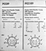
the PCC89 is the series-string version of the ECC89
Attached pic is from the Mazda (AEI) 1970 short-form data book, with the frame grid 189 for company.
Full data:
https://frank.pocnet.net/sheets/129/p/PCC89.pdf
the PCC89 is the series-string version of the ECC89
Attached pic is from the Mazda (AEI) 1970 short-form data book, with the frame grid 189 for company.
Full data:
https://frank.pocnet.net/sheets/129/p/PCC89.pdf
Attachments
Yes, µ is fairly stable; but in the triode's intended purpose (Cascode for tuner) it's S that makes the AGC able to control gain - and S has a wide range...
Mu is about 26 and not variable.
My testing confirms this with the two samples I've tried using the triode with the grid connected to the screen.
What tests have you done ? How you can connect grid to screen in a triode ? 😀
A variable mu stage is like an electronic potentiometer for a small input AC voltage , when grid voltage is changed from 0 to -15 lets say , you will get gain variation from 35 to 0,35 ( 100x range ) at least , amplification and attenuation . It is important that the input AC voltage to be small < 100mVrms , otherwise it will modulate the gain itself and produce distortions .
I tested this in PCC189 , one triode simple common cathode stage amplifier
The graph showing mu constant with anode current is not necesary proving anything , as the mu variation is a function of grid DC voltage . You can have in theory any anode current with maximum amplification if you change the stage anode , cathode resistors .
Last edited:
Every triode is a "voltage controlled resistance"... So what? They are all like an electronic potentiometer. It's only linearity that changes IMHO.
You can fudge any reading with f*ckery and an asterisk. (workarounds, feedback, etc)
You can fudge any reading with f*ckery and an asterisk. (workarounds, feedback, etc)
My apologies, by screen I meant the shield between the two triodes that is internally connected to the first triode's grid. My tests were for the device's suitability as a driver for a 6A3. They were cheap so I figured why not. I checked for gain and distortion with a CCS on the plate, and a 2 watt multiturn potentiometer bypassed with a 560uf capacitor to establish bias. The load was 100k capacitor coupled. Distortion measurements were taken using the FFT function on my oscilloscope. The resolution isn't great, but the tube would oscillate when hooked up to my soundcard. I could add a source follower to isolate the laptop from the load, but the harmonics were too high for my liking for that amount of work.
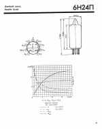
The curves I was looking for were from Tube Tester Files - 6N24P - 6H24P
Unfortunately, my results didn't match. For example at -5 volts 10ma my plate voltage was 175. . I don't have anything written down, but I did just get home and have a small bit of time before my weekend starts. I will try to get some concrete data to share.
Every triode is a "voltage controlled resistance"... So what? They are all like an electronic potentiometer. It's only linearity that changes IMHO.
You can fudge any reading with f*ckery and an asterisk. (workarounds, feedback, etc)
So that's the reason they invented variable mu tubes ... a normal triode is not like that , the effect is very small , go check 😀
The purpose of this is of course to modify the gain in a tuner so the demodulated signal is constant for weak / strong stations , it is called automatic gain control .
Last edited:
Yes, I get that.
Am I right to think the remote cutoff pentode was developed after these cascode tubes?
Am I right to think the remote cutoff pentode was developed after these cascode tubes?
Ok, did a quick and dirty... All points measured at 10ma.
-1 volt grid 60 volts plate
-2 volts grid 94 volts plate
-3 volts grid 125 volts plate
-4 volts grid 150 volts plate
-5 volts grid 177 volts plate
-6 volts grid 200 volts plate and over dissapation
-1 volt grid 60 volts plate
-2 volts grid 94 volts plate
-3 volts grid 125 volts plate
-4 volts grid 150 volts plate
-5 volts grid 177 volts plate
-6 volts grid 200 volts plate and over dissapation
- Home
- Amplifiers
- Tubes / Valves
- 6n24p / 6H24∏