Hi krivium,
If what you are saying is correct, would you know how the commercial manufacturers decide on the Q since they (mostly) have no control over the customers' room? Is there a "compromise" Q that they gravitate to?
Kindest regards,
M
. . .
Camplo, you focus on only one part of a couple: the point being the room+drivers to behave as a system.
If you are into a 'bunker' ( cement walls) there is chance sub 0.577 will be of help to have a coherent 'couple'.
If you are outdoor a sealed 0,577 Q box will sound anemic. Here Q of 1 or more might help compensating... at least from a frequency point of view ( but impulse will ring).
. . .
If what you are saying is correct, would you know how the commercial manufacturers decide on the Q since they (mostly) have no control over the customers' room? Is there a "compromise" Q that they gravitate to?
Kindest regards,
M
Seems my hypothesis may have well been correct....correct like...has some correctness in it...
I foresee the issue of lack of specificity. I've seen critical damping cited as 0.5, 0.6, and in the article in the link its 1. For Qtc I figured 0.5 was where its at....
Where in the IR would we look to see the missing harmonic info?With overdamping, some of the higher frequency harmonic waveforms will be lost (remember that these are the waveforms which already have a lower amplitude; with more damping their amplitude disappears to near zero).
I foresee the issue of lack of specificity. I've seen critical damping cited as 0.5, 0.6, and in the article in the link its 1. For Qtc I figured 0.5 was where its at....
Last edited:
If what you are saying is correct, would you know how the commercial manufacturers decide on the Q since they (mostly) have no control over the customers' room? Is there a "compromise" Q that they gravitate to?
M
Hi Mefistofelez,
I can't tell. I come from pro studio so i know for some ( big) systems and for some ( nearfield) monitors but it is a different field than home audio, domestical.
For the big main i've seen/ heard most were EBS with low to very low tuning freq. ( the same answer GM gave when we asked for best group delay alignement for vented).
For nearfield it goes from 0.6 sealed ( Yamaha NS10) to some very nasty alignement for bass reflex ( Krk can't remember the exact model with inflated low end). In between you had passive radiator ( Mackie Hr824) or the Pmc transmission line...
I know some french manufacturer of hifi ( Cabasse) used to have bass reflex which didn't goes low ( around 60hz) but with very low group delay, at least for the models i used...
Ellipson was on same league but with double or triple bass reflex ( cleans up a lot the low/low mid).
So all in all i would say it might well depend of the preference of the loudspeaker designer and the kind of target they want to touch: a bookshelf close to wall in a small room will have different needs than an Everest S9500 which use a dual tuning ( one for each woofer) with a bessel alignement as the target for asian market...
I would not like to design this kind of things because there is to much randomness.
I will let GM explain how the clipping plays out because I'm just hypothesizing.
In regards to my td15m
I'm pretty sure this picture says it all unless there still a deeper connection to the results it displays.... With the DATSV3 as an amplifier and the Yamaha HTR as an amp....Damping has changed at F.....The level has been spl matched, mic position unchanged.....What is wrong with the DATSV3 that would not allow it to allow the driver to damped the diaphragm......Half Qes it seems to be exact? Qes is obviously higher with the Yamaha...
It measured the 8ohm woofers properly...so something about 16ohm is stopping the DATS from being accurate is my guess. Voltage is being clipped maybe...
I have to ask again; how is this measurement made? Are you treating the DATS as an audio interface, and using REW to make the sweep? That isn’t how that device is meant to be used…
If so, you need to consider that the DATS v3 has a resistor on a loopback internally. The DATS software measures this resistor value and uses it as a calibration. REW has no idea about this, and will not compensate the response.
If you want to make a fair comparison, use the DATS software to make a measurement of TS parameters, and save the impedance complex magnitude data. Repeat the test using the Yamaha HT amp, via the REW manual’s method to measure TS parameters, and compare to DATS.
It would also be worthwhile to do a straight loopback measurement of the HT amp to compensate for any built-in frequency non-linearity. A simple voltage divider made from resistors can pad the output voltage down sufficiently to avoid melting your audio interface.
Hello GM
Clipped?? Why would it be clipped?? Are you talking about driver Qts or Qtc. Both??
Rob 🙂
Like camplo stated i.e. the driver's signal decays 'faster'/quicker than it's supposed to [AKA under-damped], which the Altec guys that helped me called 'clipping' since it 'disappeared'/truncated the transient
Could be just the driver [O/IB] or the system Q [sysQ] with 'system' being just some form of speaker box alignment and/or summed in room.
Hi krivium,
thank you for the answer. I thought that I read somewhere on the forum that you had a background/worked in production(?) field, hence my question.
Kindest regards,
M
thank you for the answer. I thought that I read somewhere on the forum that you had a background/worked in production(?) field, hence my question.
Kindest regards,
M
Like camplo stated i.e. the driver's signal decays 'faster'/quicker than it's supposed to [AKA under-damped], which the Altec guys that helped me called 'clipping' since it 'disappeared'/truncated the transienttoo fast, though as an analog description, not the digital transient spike.
Hi GM,
That sounds like an oxymoron....like reducing ringing is "clipping" the ringing, and therefore not good ..????
Doesn't pass the smell test does it? What am i missing?
Like camplo stated i.e. the driver's signal decays 'faster'/quicker than it's supposed to [AKA under-damped], which the Altec guys that helped me called 'clipping' since it 'disappeared'/truncated the transienttoo fast, though as an analog description, not the digital transient spike.
Could be just the driver [O/IB] or the system Q [sysQ] with 'system' being just some form of speaker box alignment and/or summed in room.
What is the Q of a normal bass tone control? About Q=.4/BW=3?
I have to ask again; how is this measurement made? Are you treating the DATS as an audio interface, and using REW to make the sweep? That isn’t how that device is meant to be used…
You are right about that, I tried the same experiment on another woofer I have that is different impedance and the same thing happened. The easiest sensible thing I could do at this point take measurements with the HT amp and compare to where I think the roll off should be...
Last edited:
Like camplo stated i.e. the driver's signal decays 'faster'/quicker than it's supposed to [AKA under-damped], which the Altec guys that helped me called 'clipping' since it 'disappeared'/truncated the transienttoo fast, though as an analog description, not the digital transient spike.
Could be just the driver [O/IB] or the system Q [sysQ] with 'system' being just some form of speaker box alignment and/or summed in room.
Hello GM
Help me out here
Quick question. How do you separate the ability to follow the transient amplitude/frequency correctly but then decay too quickly??
If you can't do one how can you do the other??
If you are overly damped you should see attenuation and/or modification of the amplitude/FR??
That I would think would be across the board so it would not just be delay but amplitude and frequency content of the original transient.
What do you think??
Rob🙂
What is the Q of a normal bass tone control? About Q=.4/BW=3?
Q is just as ambiguous as F at times. Q of a roll off slope isn't exactly the same thing as the Q as in a damping factor thats going to manipulate decay times.
Last edited:
Ambiguity Shambiguity
It's only ambiguous in camplospeak. The real world is not. What F are you speaking of this time? Fs? Fc? F3? F...?
If these terms are ambiguous, so is the discussion.
Q is just as ambiguous as F at times. Q of a roll off slope isn't exactly the same thing as the Q as in a damping factor thats going to manipulate decay times.
It's only ambiguous in camplospeak. The real world is not. What F are you speaking of this time? Fs? Fc? F3? F...?
If these terms are ambiguous, so is the discussion.
Last edited:
Well we are all talking about Q as in woofer damping....you are talking about q as in the shape of a response/filter/roll off.... Thanks for making sure to throw your insults in there, real mature thing to do. I imagine your world is....without relief lol...you always seem real tense...on edge....like maybe its been a long time since you've had any... you typed "Ambiguity Shambiguity" and are ok to have your name attached to it...
Last edited:
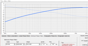
You can look at this yourself with rephase example of settings below.They stopped at 0.5....should of kept going to like 0.1 to show the trend.
FR issues can be adjusted with Filters, I am more concerned with other factors of over dampening that may occur....Dynamic compression and a loss of low level signal?
Those step response shapes cover the whole bandwidth, the sharp rise is high frequencies. A woofer or mid will not look like that with a crossover. So they can be misleading to look at without considering the context.
Lowering the Q puts increasing strain and power requirements on the system so going below 0.5 doesn't make much sense. With a second order Q of 0.2 look how high the rolloff starts, increase the Q of the filter and that moves back down.
This also comes back to time and frequency being linked. The flatter and more extended the frequency response is the better the step looks.
For some science you can look at Sean Olives preference research from 2004 which is covered at chapter 20 in Floyd Toole's 2nd edition book
When looking at bookshelf speakers two factors were dominant
"Then there are two statistics that separately focus on low-frequency performance:
■ LFX: low-frequency extension (Hz), the 6 dB down point relative to
listening window (LW) sensitivity in the range 300 Hz to 10 kHz.
■ LFQ: absolute average deviation (dB) in bass frequency response from
LFX to 300 Hz."
When it moved to a sample of 70 speakers including floorstanding ones it came down effectively to one parameter in low frequencies
■ Low-bass extension (LFX): 30.5%
So the most important factor is to extend the frequency response down as low and as evenly as possible in the room or listening space.
Attachments
I honestly thought Paul could be able to add to our conversation but slowly hes shown a lack of criticalness about his approach. In particular approaching our discussion with the mention of a "normal bass control"....As I said hes not referring to Q in the same way we are discussing regarding the clipping which seems more like a reduction of decay into the negative side of the time scale where the signal is reference 0.
Paul I don't exactly want to deal with you but I cannot make you leave....so you are at my table....my thread, purposely being abrasive....I'd like you to leave....and I'm guessing you won't....and then you are just that guy whos at a place where the person who leads the interest there, doesn't want you there, yet you are there any way lol
Paul I don't exactly want to deal with you but I cannot make you leave....so you are at my table....my thread, purposely being abrasive....I'd like you to leave....and I'm guessing you won't....and then you are just that guy whos at a place where the person who leads the interest there, doesn't want you there, yet you are there any way lol
Last edited:
I think I have done this or at least helped to do this by choosing large drivers and multiples creating large accumulated sd.So the most important factor is to extend the frequency response down as low and as evenly as possible in the room or listening space.
I am focusing on my midrange, the dual 18's do the extending. The mid will be high passed at say 80hz.
Its just getting this critical Q topic situated...in particular below critical Q. There were woofers that I really liked but the Qtc would have been 0.29 for example, and thats with 2 of them in my 230L cabs.... I was trying verify that I should actually care about 0.5 Qtc since the way these woofers will be set up, excursion will always be below 1mm in so many words. A lot of specs become null by this point is the general consensus.
Last edited:
Unless you plan to use the rolloff of the midrange in the cabinet as part of the crossover the Q of it is irrelevant as it will be completely modified by the crossover and EQ.I am focusing on my midrange, the dual 18's do the extending. The mid will be high passed at say 80hz.
The diagrams you posted are related to low frequency rolloff.
There it is again...you can't change damping characteristics with a filter. You can copy the natural roll off of other Q's but Qes/Qms are unchanged...
You can’t adjust Qtc or fs with a filter. Linkwitz transform is a sort of equalizer that simulates changes is Qtc and fs, but the actual electrical parameters for the woofer do not chance. You can add series resistor, add mass, remove mass or add magnet to really change parameters
- Home
- Loudspeakers
- Multi-Way
- Is it possible to cover the whole spectrum, high SPL, low distortion with a 2-way?