Right, it's over-damped = clipped.
Hello GM
Clipped?? Why would it be clipped?? Are you talking about driver Qts or Qtc. Both??
Rob 🙂
I don't get it either.
Camplo, you focus on only one part of a couple: the point being the room+drivers to behave as a system.
If you are into a 'bunker' ( cement walls) there is chance sub 0.577 will be of help to have a coherent 'couple'.
If you are outdoor a sealed 0,577 Q box will sound anemic. Here Q of 1 or more might help compensating... at least from a frequency point of view ( but impulse will ring).
Now you have spare time, i'm with Fluid: put things together and check by yourself the validity of results against your theory.
You could discuss theory and cause of issues ad libitum but only real life test will give you answers.
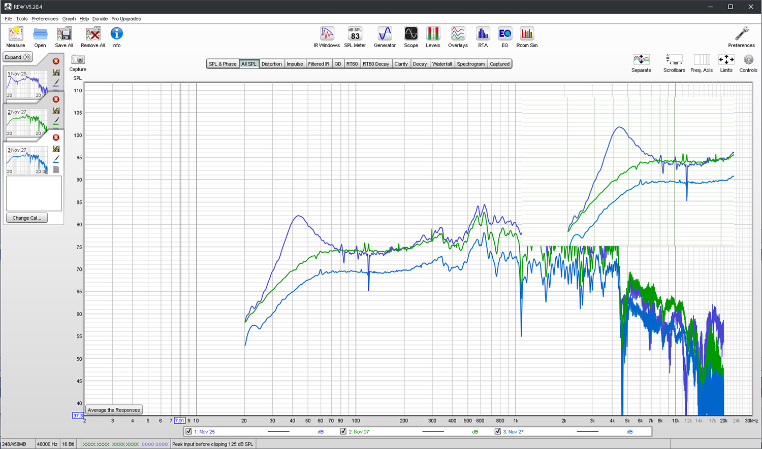
Does this answer my woofer issue? The violet trace is a measurement made with the DATsV3, the other two traces are taken with a HT receiver. One meant to volume match, another to see what happened with even lower level with receiver. I tried different input levels with the DATS in the past, and the readings were the same from what I recall.
Attachments

Last edited:
In regards to Qtc vs room Q...If the signal is getting clipped you can't just add it back with reverb.
Look at how much decay changes at F. This would be high passed in my application but I wonder if there are such large variances with the enclosure in use instead of free air.
It’s hard to understand the plots you share because they’re not explicitly labelled, and there’s little information about the test setup. If you can include that, people will be able to offer much better help or advice.
In this case, are you comparing a low voltage drive level to a high one? What are the levels? How is it driven, and how are the drive levels measured? Is the driver in a box? What box? Is it in a room? Where in the room? What type of room? What mic is used? How close is it?
All these sort of things might seem boring, but with so many unknowns the ‘issue’ could be anything - including measurement error. Which is more common than you think.
Refer to the last post, as it is the most relevant.....These are free air sitting on the ground, in a room, at 0inches
I think I have diagnosed the issue
I think I have diagnosed the issue
Last edited:
In regards to Qtc vs room Q...If the signal is getting clipped you can't just add it back with reverb.
Clipped relative to what?* Is there a definitive answer on what qtc should be? Is it true in all situation?
This is an alignement and like all alignement there is an infinity of answers with some defined points along the line ( with a 'name' or value with them, 0,707 ; 0,577,...).
Same issue with the electrical curve needed to have an acoustic curve: don't use a textbook 4Pole LR curve without first check the driver behaviour or there will be surprise...
Here is a real life example for you to bring back perspective:
https://www.diyaudio.com/forums/roo...round-listening-dimensions-2.html#post6763312
* Isn't the Qtc a three unknown equation with box volume, freq response ( hence frequency dependent level) and decay response expressed? If yes which one do you favour amongst other and why? Doesn't it compromise on other parameters? So is there a definitive answer? 😉
Last edited:
Can't wait for GM to get back to us! lol!
If 0.5 gives the "best transient" what happens below 0.5 is what I'd like to know....Clipping? Sure....more details need to be given to grasp whats happening here....Clipping would suggest a dynamic attenuation of the peak of the transient.
If 0.5 gives the "best transient" what happens below 0.5 is what I'd like to know....Clipping? Sure....more details need to be given to grasp whats happening here....Clipping would suggest a dynamic attenuation of the peak of the transient.
Last edited:
I think i understand what he wanted to say but... it is relative.
I repeat, put outdoor some sealed 0,577 qtc box and a 0,707 and 1 qtc box and listen to them.
Make the same thing inside and draw your own conclusion.
Of course close to 0,6 Qtc have an advantage if you look at impulse response only.
People focus on 0,707 Qtc because it is the more even compromise between low end extension, output level and decay. But in some rooms it won't work as it won't blend well...
If you take only freq extension as target, 0,577 doesn't make sense... you loose too much db too soon... in a way you 'clipped' what the box is able to do from an amplitude pov... even more compared to 1 or more qtc ( when you gain level around fc...).
I've got a bass amp ( combo) relying on more than 1 Qtc for a 15". A nightmare to mic in a room, perfect on 'open' space for a 4 string as it doesn't weight a ton an can compete with a soft drummer with 200w...
Don't even think to use a 5 string or perform too much slap on lows too as thermal compression will show off soon... it's always a balancing act.
Last edited:
In the context of this system, it is meant to be a mastering monitor. So what ever is the scientifically correct answer, I will respect the most. If the my woofer is within spec, and I hope it is, Qtc should be around 0.54
A perfect impulse is impossible....so I really am not sure what 0.5 or 0.6 means for critical damping.
Keep in mind damping is more than a FR or roll off slope
For similar reasons I also come to the conclusion that Qes matters even below 1mm, in the form of compliance.
A perfect impulse is impossible....so I really am not sure what 0.5 or 0.6 means for critical damping.
Keep in mind damping is more than a FR or roll off slope
You can’t adjust Qtc or fs with a filter. Linkwitz transform is a sort of equalizer that simulates changes is Qtc and fs, but the actual electrical parameters for the woofer do not change. You can add series resistor, add mass, remove mass or add magnet to really change parameters
For similar reasons I also come to the conclusion that Qes matters even below 1mm, in the form of compliance.
Last edited:
I think i understand what he wanted to say but... it is relative.
I repeat, put outdoor some sealed 0,577 qtc box and a 0,707 and 1 qtc box and listen to them.
Make the same thing inside and draw your own conclusion.
Of course close to 0,6 Qtc have an advantage if you look at impulse response only.
People focus on 0,707 Qtc because it is the more even compromise between low end extension, output level and decay. But in some rooms it won't work as it won't blend well...
If you take only freq extension as target, 0,577 doesn't make sense... you loose too much db too soon... in a way you 'clipped' what the box is able to do from an amplitude pov... even more compared to 1 or more qtc ( when you gain level...).
I've got a bass amp ( combo) relying on more than 1 Qtc for a 15". A nightmare to mic in a room, perfect on 'open' space for a 4 string as it doesn't weight a ton an can compete with a soft drummer with 200w...
Hello
They will measure and sound different but it is a spectral tilt not "clipping". Your are attenuating the low end response with a low Q box. And the reverse for a high Q
I always use low/lower Q boxes for home. Never tune for maximum flat.
Rob 🙂
They stopped at 0.5....should of kept going to like 0.1 to show the trend.
FR issues can be adjusted with Filters, I am more concerned with other factors of over dampening that may occur....Dynamic compression and a loss of low level signal?
Attachments

Last edited:
Robh3606,
We are in agreement. I was trying to understand how GM could answer (speculating).
Camplo, i know what your goal is, the example was just that an example to put things in perspective....
Could you point me to where you see a 'clipping' in the step response graph? I see a decay issue but no clip on the initial part?
And to me it is naive to think an eq will 'fix' anything without inducing it's own set of issues relative to qtc (iir: what does a linkwitz transform?).
Last edited:
They stopped at 0.5....should of kept going to like 0.1 to show the trend.
FR issues can be adjusted with Filters, I am more concerned with other factors of over dampening that may occur....Dynamic compression and a loss of low level signal?
Why would you have Dynamic Compression? This is low level right?? Why would you loose low level signal?? What is causing the loss of signal??
The "dampening" Why?? Lower Q less ringing, quicker settling times at the expense of LF bandwidth.
Rob 🙂
Ok then, in that case, a lower Q is always more desirable in the name of scientific sound quality. As long as settling times don't impede on the input signal
in a nut shell....Compliance vs Velocity... A viscous type experience can have different compliance at different velocities...where at some point of raising velocity, resistive force increase dramatically....hence the clip
my theory...
I have no idea....Ive never seen it represented. Like I said, hangin on a chair until GM gets back....In regards to decay, if compliance is so low as to muffle out a signal of low nature?Could you point me to where you see a 'clipping' in the step response graph? I see a decay issue but no clip on the initial part?
The compliance is so low it causes a clipping point on the rise of the transient? Velocity drops dramatically, diaphragm never completes cycle.... something like that...It would appear as a lowering of sensitivity when in actuality the increasing of voltage will not help proportionally and xlim/xmax has not been achieved either. Its like a xlim/xmax but in a different domain, the compliance domain....sorta like when a falling objects hits water....more like when an object moves through a gas/liquid to the point it thats causing excessive friction. Compliance is related to viscosity is probably the better way to say it. Moving through said viscous material creates "friction" that isn't directly proportional to speed.... eventually you hit a speed where friction increases greatly in proportion to increase of speed. The compliance of the driver is the viscous like experience, where if the damping is too high, resistance forces will increase greatly at some velocity within desired playback.Why would you have Dynamic Compression?
in a nut shell....Compliance vs Velocity... A viscous type experience can have different compliance at different velocities...where at some point of raising velocity, resistive force increase dramatically....hence the clip
my theory...
Last edited:
Scientific sound quality?!
Please Camplo give a definition and where you have seen this used! 😀
I bother you but really this doesn't make sense to me: it's a question of priority on your design criteria list, nothing more in my view.
You want to favor transient response, then yes critical damping may be your target. Once you introduce your room into the equation ( or the lack of) then it might change... to lower or higher Q if you use small diameter drivers and your room don't respond well to the lower range... 😉
You never seen it represented because a step is a step ( square) and by definition it is... clipped! 😉
The interesting points are the decay and first 'negative' bounce ( on the negative occurence): theorically this shouldn't exist, the smaller it is the better. As can be observed there is more chance for the system that compliance be too high and the system ring. Yes compliance might be too low but you'll encounter other issues ( freq) before it happens so there is low chance to face it ( like with the 'group delay affair' some month ago... your concerns may be valid but in practice you'll never encounter them as they are 'bad practice' and you target the opposite).
Last edited:
As you pointed out krivium ... typically a smaller room would favor lower "Q" enclosures. Higher "Q" enclosures in smaller rooms tend to sound boomy and ring. Enclosure "Q" below 0.5 starts to qualify as an infinite baffle alignment.
Refer to the last post, as it is the most relevant.....These are free air sitting on the ground, in a room, at 0inches
I think I have diagnosed the issue
Ok; on the ground is not free-air / free-space. It’s nearly, but not quite, half space. This will massively influence all of the data, and if this is how you’ve taken your DATS measurements so far then that might explain a lot.
For example, there is a reflection from the floor in this measurement. Regardless of mic placement relative to cone- which can’t be truly 0, because the cone would hit it, right? Anyway, this alone can explain a big increase in ringing at Fs, because you’re measuring the mirror image source “in the floor” as well.
Measuring TS parameters requires significant free space around the driver - several metres - and the unit must be suspended away from any boundary. Hanging it by a wire from one of the basket mounting holes is one way to do that, or you can make a pair of upright strips floor to ceiling, and bolt the driver to that.
To get complete data, you also need to add a known mass to the cone or put it in a known, sealed box volume. The former is best done with some small magnets, placed on the centre of the dust cap.
If you’re not doing that, then you’re not getting close to manufacturer methods regardless of the drive voltage level. Trying it again as above could save a whole lot of back and forth and possibly making a manufacturer look bad, as well as helping you investigate the theories you have.
Good scientific method minimises the numbers of variables in an experiment, after all!
Should you want to test at different drive voltages, there’s a schematic and description of how to measure TS in the REW manual. You need a known value of good quality resistor which can handle the voltage required, a bit of wire, and some crocodile clips. That’s all that’s inside the DATS box, in fact 😀
The compliance is so low it causes a clipping point on the rise of the transient? Velocity drops dramatically, diaphragm never completes cycle.... something like that...It would appear as a lowering of sensitivity when in actuality the increasing of voltage will not help proportionally and xlim/xmax has not been achieved either.
Hello Camplo
OK I think I get what you are saying. Compliances are essentially cone terminations no? They are tuned so why would this be an issue over a drivers designed bandwidth?? Why would the diaphragm not complete a cycle if it hasn't reached it's mechanical limit?? A portion of the waveform could be attenuated depending on the bandwidth of the driver. All drivers act as lowpass, bandpass or high pass to varying degrees so as long as you stay where you should where is the issue??
Rob 🙂
I will let GM explain how the clipping plays out because I'm just hypothesizing.
In regards to my td15m
I'm pretty sure this picture says it all unless there still a deeper connection to the results it displays.... With the DATSV3 as an amplifier and the Yamaha HTR as an amp....Damping has changed at F.....The level has been spl matched, mic position unchanged.....What is wrong with the DATSV3 that would not allow it to allow the driver to damped the diaphragm......Half Qes it seems to be exact? Qes is obviously higher with the Yamaha...
It measured the 8ohm woofers properly...so something about 16ohm is stopping the DATS from being accurate is my guess. Voltage is being clipped maybe...
Attachments

Last edited:
- Home
- Loudspeakers
- Multi-Way
- Is it possible to cover the whole spectrum, high SPL, low distortion with a 2-way?