Look up the formula, its quite simple
I even posted a link on the previous page 😀 but since I get the impression that camplo doesn’t tend to follow those:
Attachments
Sorry but I dont follow you at all
You are reading a reply that was directed at B_force
I didLook up the formula, its quite simple
I never suggested a way.And parameters can be changed, just not the way you suggest
God forbid I ask a question, I'm sure I was trying to execute the formula correctly while asking about it...If you are so thorough why didn't you list the units needed for the formulas 😉 😀I even posted a link on the previous page but since I get the impression that camplo doesn’t tend to follow those:
Adding a resistor will change Parameter. It is the way that I could take a 8ohm AE15TM and reach the parameters I have now with my 16ohm Woofer but maybe not the only way.
Where I am stuck at is this issue of CMS/RMS and the idea of a looser suspension being more accurate at low volumes and stiffer suspension "opening up" with more volume.....
Is this really true? I asked in another thread and I only got the vibe that it can be true but its not that simple. Sorry I don't know if I can get Klippel measurements on all these woofers, is there a way to discern this aspect through Thiele specs?
I really don't know
At 233 Euro each when buying two it seems like a pretty good deal, pull the trigger before they are gone 🙂
I am doing my best to find a reason to not send this AE15TM back....My question to B_Force might provide clarity.
My issues with CMS are holding back from purchasing a woofer. The surrounds on the Oberton have half the CMS of the AE woofer.....Rms is still very close though.....I would think that Rms mattered more.....
Also, IF I change Resistance.....How Does this Change Inductance....I did not see the connection within the formulas I've viewed so far kyleneuron
Speaker impedance is the total sum of two things:
The resistance of the long winding of wire making up the voice coil.
A special magnetic property called inductance created when the wire is wound into a coil.
This suggest that more wire length raises inductance if I interpret that correctly. I measured a 0.38(10khz) and spec is 0.22.......So mine is about Dbl.... does this reflect dbl the length of wire? Seems like wire thickness would play a factor too...
Last edited:

I am doing my best to find a reason to not send this AE15TM back....
The best reason is AE make you what you asked for. Accept it.
AE designs drivers. System design is the customers responsibility.
Last edited:
Paul don't start with me, I asked for a woofer with a Qts of .33 and 16ohms...It was John who noted that the TM was off.
why do you push lies so hard?
Get yourself banned while your at it why don't ya...
why do you push lies so hard?
Get yourself banned while your at it why don't ya...
Last edited:
I don't 'push' anything. I don't lie. Don't threaten me with a ban for telling the truth.
If John noticed something was 'off', why do you have the unfixed driver?
If John noticed something was 'off', why do you have the unfixed driver?
Last edited:
Le is proportional to the square of turns. The turns in the gap contribute more than the ones that "stick out".
Regard
Wire thickness does not play a part?
Basically a higher Re driver as the result of Longer wire, should increase Le but to say exactly how much is beyond me. I am measuring a0.38 like I say
One thing I am noticing is that Le is placed out of speculation with a lot of these drivers just by leaving out the information regarding Fle.
Ae list the Le as .2 while the Oberton list Fle 1khz and Le 1.01Mh
Dats says my woofer le is 2.2Mh at 1000hz....So my thought is that the 8 ohm version like has a le at 1000hz around 1mh also???
Last edited:
I don't 'push' anything. I don't lie. Don't threaten me with a ban for telling the truth.
If John noticed something was 'off', why do you have the unfixed driver?
Why is it your concern? are you personally vested? I have the Driver because I am trying to not waste his or my time. The report of parameters is not a cut and dry thing just like Fluid pointed out in a few previous post.
If the specs AE operate by are generated in a way that I do not have the ability to replicate then that could be an issue. Actually a big issue because he will measure it, it will check out fine, and then what.....Time/Money wasted.
John has given me permission to send them back and if they are off he'll take care of it....So I am trying to get to the bottom of this before sending it, because I just may figure out something critical to my choice...as you can see, I am researching currently. For the first time in several months actually because I have the time to do so...not that it matters to yoooooooooooou lol
even in your reply you lie...I'm not threatening you with a ban.
lets start a count of them, so far you are at 2.
Actually make that 3 "I don't lie" - suggest that you have never lied ever, which is impossible.

Paul you are educated about speakers why not add to the discussion in a positive way. B_force made a statement that is worth discussing. You could help me reverse engineer the AE driver I have or you could be abrasive and aggravating to which, I give you no inspiration to do so, other than your obvious passion towards Acoustic Elegance, are you guys having sex? As I've said before this one little issue does not sum up a company and I've had nothing but positive experiences with them so far. Calm the Fs=cutoff down.
The only "evidence" I would take seriously, are Klippel measurements, like the once on VC Testbench.
All the rest are just little unsupported little theories.
More often than not, not correlating well with actual measurements.
Sounds like hes saying Thiele specs vs sonic measurements.
Last edited:
Speaking for myself .... not enough.(snip), are you guys having sex?
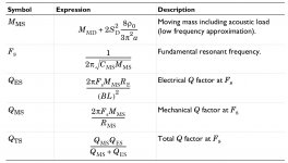
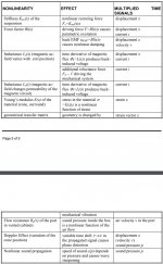
Also interesting is the different performance had at different voltage. Something I should considered since I will desire low voltage playback at some time. Below are some free air measurements of my fresh woofer. I bet over time as a woofer breaks in, the difference in performance at different levels, starts to even out.
I am really curious to this idea that driver with a lower CMS value are not accurate to transients at low Volume.
High Volt
Low Volt
Notice the performance at Fs
puppet - lol!
I am really curious to this idea that driver with a lower CMS value are not accurate to transients at low Volume.
High Volt
Low Volt
Notice the performance at Fs
puppet - lol!
Last edited:
Sounds like hes saying Thiele specs vs sonic measurements.
The LPM and LSI modules from Klippel use electrical measurements. Those are the ones used by most speaker designers; small and large signal parameters, as a function of excursion.
The other modules are more focused at R&D of transducers or complete systems. If you ask nicely, and explain why you’d like to see it, many transducer manufacturers will share a Klippel dB-Lab file with you.
I feel like I've simplified it so that a plethora of 15"s could pull this role off and sound pretty much sound the same.... Am I wrong?
You are correct. That's what I always do.
Regarding TS measurements, I used to plot them versus level. Start high and go low - reduces the thermal variations. You can tell a lot about driver quality that way. Psuedo-Klippel.
Then I misunderstood, I thought you had already sent them back.I am doing my best to find a reason to not send this AE15TM back....
Differences in measurement conditions presents a real problem when trying to confirm a manufacturers parameters. Have you asked John how he measures them?
Why not put one in the box you made for it and measure it's frequency and impedance response. If it gives you the desired response there is no problem to be concerned about. Rig up a crossover with one of your horns and listen.
The actual parameters will change but the relative differences shouldn't change much.I bet over time as a woofer breaks in, the difference in performance at different levels, starts to even out.
There are a lot of theories related to single parameters, they can't all be true. There has been a lot of research and blind testing to work out the basics, following those seems more likely to result in success.I am really curious to this idea that driver with a lower CMS value are not accurate to transients at low Volume.
"There has been a lot of research and blind testing to work out the basics, following those seems more likely to result in success" - is there something in particular you think I might be interested in reading regarding woofers at low voltage. Part of my technique for EQing while sound engineering involves low level monitoring but I never knew how much the performance could change with level input outside of power compression and maybe suspension strain.
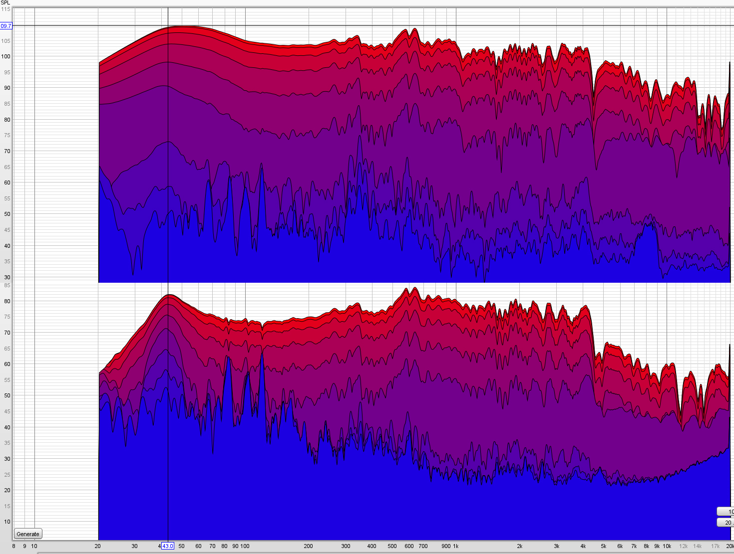
Look at how much decay changes at F. This would be high passed in my application but I wonder if there are such large variances with the enclosure in use instead of free air.
Look at how much decay changes at F. This would be high passed in my application but I wonder if there are such large variances with the enclosure in use instead of free air.
Attachments

Last edited:
This idea of critical damping 0.5.....what exactly happens when the Qtc goes below 0.5? It sounds like its a simple question but whats not making sense is that the room can raise Q.....but it can only transmit whats given to it in the first place so if a sub 0.5 Qtc box+driver is literally cutting out signal completely from the picture.....it never makes it to the room. Hopefully I am not completely misunderstanding critical damping.
With an qtc over 0.5 we have excess decay with a qtc under 0.5 we have truncated decay is how I take it.
With an qtc over 0.5 we have excess decay with a qtc under 0.5 we have truncated decay is how I take it.
You are correct. That's what I always do.
Regarding TS measurements, I used to plot them versus level. Start high and go low - reduces the thermal variations. You can tell a lot about driver quality that way. Psuedo-Klippel.
In the discussion we had in B_Forces thread regarding F, BL and le for midrange, the point was made that excursion below 1-2mm results in domination of the le factor...Q specs at these low voltage levels should be considered as well but as said in that thread, we will avoid F with a midrange. Supposedly Q only matters at F for this type of approach but looking at the decay charts I posted, you can see compliance is changing well above F at different input levels.
I would hypothesize Qes vs Mms is actually still important at low excursion even above F. Qes is the influence that still exist at these miniscule excursion's just like Le....Does that mean one would aim for a Qes 0.5? Does the Q unit transfer to the different Q factors? Meaning for example a Qts 0.5 driver in free air is critically damped like a Qtc 0.5.... My theory would be that Qes vs Mms plays a factor in the decay performance at low signal
Last edited:
With an qtc over 0.5 we have excess decay with a qtc under 0.5 we have truncated decay is how I take it.
Right, it's over-damped = clipped.
- Home
- Loudspeakers
- Multi-Way
- Is it possible to cover the whole spectrum, high SPL, low distortion with a 2-way?