"I'm hopeful to swap a few resistors etc. around and at least make a reasonable amp out of this."
The "hope" is good thing ... but the measuring tells the truth. 🙂
If it has same OPT, than A10, trust in hope ... but measuring..... 😛pp
The "hope" is good thing ... but the measuring tells the truth. 🙂
If it has same OPT, than A10, trust in hope ... but measuring..... 😛pp
Attachments

euro21,
Is the A10 Output transformer bad, or is it good?
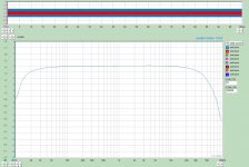
Is your frequency response graph with, or without, negative feedback?
-1dB at 30Hz, and -3dB @ 15Hz.
That is better than many of the loudspeakers that many readers of this thread have.
-1dB at 12kHz, and -3dB @ 22kHz.
That is better than many of the ears that many of the readers of this thread have.
Peel the outer layers off of the Onion first, before worrying about the inner layers of the Onion.
Just my opinion.
Is the A10 Output transformer bad, or is it good?
Is your frequency response graph with, or without, negative feedback?
-1dB at 30Hz, and -3dB @ 15Hz.
That is better than many of the loudspeakers that many readers of this thread have.
-1dB at 12kHz, and -3dB @ 22kHz.
That is better than many of the ears that many of the readers of this thread have.
Peel the outer layers off of the Onion first, before worrying about the inner layers of the Onion.
Just my opinion.
Last edited:
"Is the A10 Output transformer bad, or is it good?"
Are you kidding? 😛
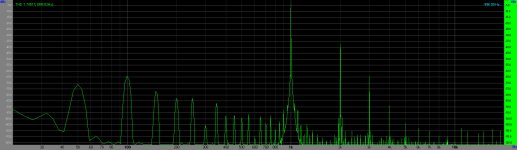
False impedance (thus enormous distortion in this design, with this tube even at minimal power), resonants in main bands driving 700R impedance!!!
With 13dB dip at 40kHz any OPT usable .... maybe in car radio at 1960, not elsewhere.
"That is better than many of the ears.."
This is an advantage for a hearing aid, but it cannot be a consideration in a design of "HiFi" equipment.
p.s.
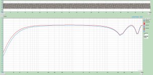
for comparison this is my 801a PSE transmission curve (at 1W, 0.86% THD) with cheap custom wound 5k transformer.
Are you kidding? 😛
False impedance (thus enormous distortion in this design, with this tube even at minimal power), resonants in main bands driving 700R impedance!!!
With 13dB dip at 40kHz any OPT usable .... maybe in car radio at 1960, not elsewhere.
"That is better than many of the ears.."
This is an advantage for a hearing aid, but it cannot be a consideration in a design of "HiFi" equipment.
p.s.
for comparison this is my 801a PSE transmission curve (at 1W, 0.86% THD) with cheap custom wound 5k transformer.
Attachments
Last edited:
Maybe I'm missing something but why would the behavior of an OT at 40kHz matter to someone whose hearing is limited to less than that? Which is everyone, since nobody's hearing goes that high even when they're young."Is the A10 Output transformer bad, or is it good?"
Are you kidding? 😛
False impedance (thus enormous distortion in this design, with this tube even at minimal power), resonants in main bands driving 700R impedance!!!
With 13dB dip at 40kHz any OPT usable .... maybe in car radio at 1960, not elsewhere.
"That is better than many of the ears.."
This is an advantage for a hearing aid, but it cannot be a consideration in a design of "HiFi" equipment.
p.s.
for comparison this is my 801a PSE transmission curve (at 1W, 0.86% THD) with cheap custom wound 5k transformer.
How and why does this have an effect on the audible frequency range?
I'm also wondering if you're measuring the same OT as the one in Stephe's amp. Earlier you seemed to be saying that the primary actually measured 5k but she measured the ones in her A12 and they're 3.2k with a tap at 50%. Perhaps the A10 and A12 use different OTs.
Oh, and I'm curious . . . who made your custom wound 5k OT and how much did it cost? Just trying to put the term "cheap" into perspective.
Last edited:
@Flacharlie
"primary actually measured 5k "
#2 post: "rather 3k5 than 5k"
If it would be 5k, such distortions would not arise.
"they're 3.2k"
I found the removed A10 OPTs data, and based on the measured RLC parameters rather 2k8 than 3k2.
That explains the early growing distortions.
"How and why does this have an effect on the audible frequency range?"
Install this part, which have such anomalies (even measured lower source impedance than EL34) in -relatively- close to transmission band higher edge (BTW how wide this? 😛 ), and you get such phase which flying away within the "audible frequency range".
Experienced, that such OPT which have dips or peaks under 100kHz, in the amplifier sounds worse, than which have "smooth run".
See any OPT manufacturer datasheet.
"who made your custom wound 5k OT and how much did it cost? "
One of my local DIY fellow made coils (for specified core), and I finished it with my spare Waasner core.
It -the coils- cost me about 70USD.
I find it very difficult to understand what you're saying. Not meaning to be critical but there is apparently a language issue here. Of course, I don't know any Hungarian, so you're doing much better than I ever could!@Flacharlie
"primary actually measured 5k "
#2 post: "rather 3k5 than 5k"
If it would be 5k, such distortions would not arise.
"they're 3.2k"
I found the removed A10 OPTs data, and based on the measured RLC parameters rather 2k8 than 3k2.
That explains the early growing distortions.
"How and why does this have an effect on the audible frequency range?"
Install this part, which have such anomalies (even measured lower source impedance than EL34) in -relatively- close to transmission band higher edge (BTW how wide this? 😛 ), and you get such phase which flying away within the "audible frequency range".
Experienced, that such OPT which have dips or peaks under 100kHz, in the amplifier sounds worse, than which have "smooth run".
See any OPT manufacturer datasheet.
"who made your custom wound 5k OT and how much did it cost? "
One of my local DIY fellow made coils (for specified core), and I finished it with my spare Waasner core.
It -the coils- cost me about 70USD.
For example, when I read "rather 3k5 than 5k", I assumed you meant that the OT you measured was 5k and that the tube would rather see 3k5. The OT Stephe measured was 3.2k. Not 5k or 2.8k.
The data sheets for the EL34 SE specify either 2k, 3k or, in the case of Mullard, 3.5k, depending on the operating point being used.
Are you saying that your chart is based on data measured by someone else? Or did you actually test the transformer yourself? If you took someone else's data and just ran a simulation of some kind, I would tend to question the results.
I still don't understand how something that's happening at 40kHz could affect the audible range. It seems just as likely to me that, if you know that something strange is happening at 40kHz, that it has a purely psychological effect on your perception of the sound.
Thanks anyway for trying to explain.
Last edited:
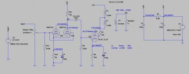
As I wrote, I bought second hand cheap A10, only for the case.
Before I took apart it, I listened it: mediocre, flat sounding.
I measured it, and measured the OPT too, because I didn't want to believe that it is possible to sell with such parameters as I measured in amplifier.
Typical "cheap chinese" product, nice look, only such value, than the price allow it.
As the schematic (some variation in the internet) shows, with this tube and this operating point the better loading is 5k -rather than 3k5-, maybe not a coincidence that some user use it with 16 Ohm speaker on 8R tap.
Attachments
As you say there are other possibilities for output tubes. The 7591 is now available in a new JJ version and that could be an easy swap. Easy to drive with an EL84 in triode for instance because of its higher gain.
Doing further research, this tube looks interesting and might solve some of the constraints I am finding myself being cornered into! That's the problem with fixing an existing product, I can't just say "OK bias the tubes with more current" when the PT is unknown and already runs hot. Same with the output load they can deal with.
I believe there is an alternative OPT smaller in size for the PCB version. Looking at the Chinese site - PTP version is larger.
I believe there is an alternative OPT smaller in size for the PCB version. Looking at the Chinese site - PTP version is larger.
Or they potted the same OT into a larger can 😛
euro21,
I asked about your graph in Post # 21: "Is your frequency response graph with, or without, negative feedback?"
Global, Schade, UL, Cathode feedback, combination of 2 or more of those, or no negative feedback?
I do not have the time to look up schematics of all the similar models of inexpensiveChinese amplifiers.
It seems that they even change the circuit, even for the same model number.
And I would not trust the output transformers to be all the same on the complete various production runs of any given model number.
Thanks!
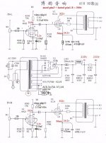
One of from the internet.
Mine (the A12) is similar, except they have 500ohm on the cathode of the EL34 biasing it even colder.
If the manufactured OPT would fulfil these parameters, the amplifier just issued (nearly) 6W with 4% distortion .... but the OPT behaviour will remain so I measured: the first resonance at about 42 kHz, so phase shift at 20kHz remains about 60 grad.
Attachments

One question:
What is the leakage reactance from the 60% primary windings (the plate to the UL tap),
to the 40% primary windings (the UL tap to the B+ end of the primary)?
For UL, and without any global negative feedback from the secondary, then . . .
the leakage reactance from 60% to 40% is paramount. That will effect the UL negative feedback . . .
no matter what the leakage reactance is from the primary to the secondary.
And, Global negative feedback from the secondary has its problems on many inexpensive output transformers.
But some of these Chinese EL34 amplifiers output transformers do not even have the UL tap.
Without a UL tap . . .
Using Pentode mode, it needs either Global negative feedback from the secondary, or Schade negative feedback.
Saturation of low frequencies that is agrivated by negative feedback is worse with Global than with Schade.
Using Triode Wired mode, it may work ok with no negative feedback, but the power output will be very low.
As to Phase problems, how many of you 'knowingly' listened to many early CD players that used a single DAC, and switched the single DAC output between the Left and the Right Channels (DAC output samples @ 88.2k/sec).
The phase of Left versus Right channel was 90 Degrees at 22.05 kHz.
Oh . . . You did not even know that many early CD players used only 1 DAC?
Back to the layers of the Onion.
Just my opinions.
Last edited:
Hi Skunkie,
Your videos are great. Cannot wait to see what you will do with this China amp. As you likely have found, a single ended zero feedback EL34 amp is noting new. Should be able to get 6W or so out of it. EL34 SE3
Good luck!
These are the operating points I am shooting for, but some people say keep the plate at 300V. I wanna see 380V like this is showing lol I'm gonna go with what I know works.
If you feel extra ambitious, you might experiment with running the output stage full pentode, and bring feedback from the output valve's anode to the driving valve's cathode. Output valve's G2 can be supplied from the same point as the driver's B+ supply - it's stable for sub-sonics.
Because there's significant DC current in the feedback resistor, both it and the driver valve's cathode resistor need to be considered together. (Please don't try to cheat and use a series capacitor, tempting though that may be, because it would unload the output transformer at very low frequencies).
Both stages in the original are starved for current, so you might want less driver stage cathode voltage than stock. To get a handle on where to begin, one would choose an input signal voltage sensitivity for full output, and decide to call that the driver's cathode signal voltage. Then calculate signal voltage at output valve's anode for full output. The ratio of these voltages is (fairly close to) the ratio of feedback resistor to cathode resistor.
That cathode resistor has both DC current from the driver valve and from the feedback resistor, so one must juggle, but it can all be done on paper. A little effort, but high performance. I'd be tempted to bring the driver's anode voltage down a lot, maybe to +170 or so, maybe less.
All good fortune,
Chris
Early single DAC Cd players don't really have a phase shift difference between channels, but rather a time shift. It's about 1/4 inch at speed of sound, so not terrible.
Other points regarding phase shift problems in output transformers are certainly important if we're trying to run feedback around them. Folks doing DIY are developing better solutions these days, and yea for them!
All good fortune,
Chris
Other points regarding phase shift problems in output transformers are certainly important if we're trying to run feedback around them. Folks doing DIY are developing better solutions these days, and yea for them!
All good fortune,
Chris
I'd be tempted to bring the driver's anode voltage down a lot, maybe to +170 or so, maybe less.
All good fortune,
Chris
I think whatever route I go, the plate resistor on the driver needs to be a bit larger and probably needs a lower cathode resistor. Like go from 75K to 100K and 1.2K or maybe just use a 1.6V led + 200R resistor on the cathode like I have used in many other amps.
Waiting on some tubes and a few parts before the real fun begins 🙂
- Home
- Amplifiers
- Tubes / Valves
- Reisong A12 review