Nice!
BF245A or B should be OK.
Once installed, you can check the Vds DC voltage: it should be >1.5V and <4V
BF245A or B should be OK.
Once installed, you can check the Vds DC voltage: it should be >1.5V and <4V
OK, I put on BF245 and its alive! But I can't find the correct Vds. With A is 5V and with B is 0,5V. Should I adjust the load?
But I can't find the correct Vds. With A is 5V and with B is 0,5V. Should I adjust the load?Then use the A, and decrease R3 to 560 ohm and increase R4 to 2K2.
Note that if the 5V is measured with a fresh 9V battery, your tester should already be functional.
Note that if the 5V is measured with a fresh 9V battery, your tester should already be functional.
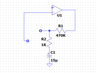
I just realized that I forgot to include the gain networks on the schematic.
This means that both stages work in unity-gain for the wide mode.
Sorry for that omission guys, I tripled-checked the schematics, but I missed that one.
Here is the correction:

C1 and R2 are the additions
Fortunately, it doesn't impair the usual operation modes of the tester. This signal-tracer function was among the various bells and whistles, but it is annoying anyway.
MagicBus, this shouldn't be too difficult to retrofit on your already built PCBs, if you want it.
I will update the schematic later
This means that both stages work in unity-gain for the wide mode.
Sorry for that omission guys, I tripled-checked the schematics, but I missed that one.
Here is the correction:
C1 and R2 are the additions
Fortunately, it doesn't impair the usual operation modes of the tester. This signal-tracer function was among the various bells and whistles, but it is annoying anyway.
MagicBus, this shouldn't be too difficult to retrofit on your already built PCBs, if you want it.
I will update the schematic later
Attachments
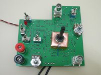
I used a bench psu to have control of the current at first power on, so with a battery could be fine. I have a few BF245a to try to select one that fits. The additions seem easy and will also be included to the pcb, no worries. The circuit seems to work for starters. It's buzzing and reacts to the controls. The final pot controls the volume while the gain pot and switch alter the pitch. The pcb ground plane apparently does its job. Only things found to be sensitive to touch on the controls side are the gain pot and the rotary switch, easy to shield so I may get away shielding only the components side.

BF245A Vds=4V with 2k2 drain, 560 ohm source resistors and a battery that measures 8,5V. RC networks in place. Not calibrated yet. As is, I get reaction only at the "wide" mode. With the magnetic probe it goes crazy when pointing a power cord. Some preliminary shielding tests suggest that shield works better when not grounded. Anxious to see how it does when calibrated.
Anxious to see how it does when calibrated.4V is OK.
Strange that you have reactions in wide mode, and even stranger is the behavior with the magnetic probe + power cord.
The cord has two closely spaced conductors mutually cancelling their fields, at least at a distance: when the probe is close enough, it can preferentially sense the field from one of the conductor and react.
The observation about the shield grounding is equally puzzling: it should work really well only when grounded.
I suspect that your probe acts mostly as an E-sensor, maybe due to a broken connection or something similar.
Make a quick and dirty test with an improvised probe: a test cable connected with any choke, 1mH or anything.
It should react mostly to the H-field.
If the 50Hz filters are unadjusted, they could severely reduce the sensitivity, but not obliterate it completely
So, I proceeded with the calibration and was able to complete the first part involving U1B but not the part with the U2B. Signal goes to input but nothing at the output so I guess I have a defect LM324. It has to wait until Saturday.
EDIT: OTOH it's buzzing so at least a part of LM324 is alive...
EDIT: OTOH it's buzzing so at least a part of LM324 is alive...
Last edited:
I think there is a missing link in the schematic to complete the feedback loop around U2B or is it?
Thanks @Elvee It is an upscale and improvement of Carlson labs Signal Sniffer !! I have to make one 😛
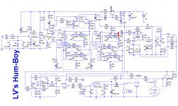
Yep, another omissionI think there is a missing link in the schematic to complete the feedback loop around U2B or is it?
 .
.Sorry about that, here is the schematic with the missing link in red:
Attachments
Thanks, but prudently wait until poor MagicBus has weeded out all of the mistakes/omissions.Thanks @Elvee It is an upscale and improvement of Carlson labs Signal Sniffer !! I have to make one 😛
This project was pen and paper only, meaning I had to transcribe the final schematic into an electronic form, which generated a number of errors.
Errare humanum est, and I am undoubtedly human....
Fixed! I did a quick calibration for starters and seems to work as it should. Now it is sensitive to hand contact only in 50Hz and wide mode, completely immune to 100Hz and 150Hz. Plausible I think... I'm going to take another round with more careful calibration when I find some time. For now, I had to turn the trimmers all the way to one end to get max signal. But I'm not sure I was patient enough. Any idea what should be the max peak to peak voltage?
Good! It's more like it.
High sensitivity to hand effects in 50Hz is normal. However, some sensitivity in 150Hz mode should also be present, unless your mains is exceptionally undistorted.
100Hz is normally never present outside of a supply, thus the absence of reaction is normal.
If the trimmers need to go to the end stop, it could mean that your caps are borderline regarding tolerance.
The adjustment range can cope with 5% caps and 1% resistors, but if you are really unlucky, you might have no margin at all .
The peak to peak voltage is difficult to predict accurately, because the gain depends on the FET and also a little on the opamp's open loop characteristics.
This is why you need to make sure your adjustment has actually reached the maximum.
Depending on which side the trimmer is, you can either momentarily add a small cap in parallel with one of the tuning caps, C7 or C8 for the 50Hz (15 or 22nF for example), or add a large parallel resistor to R56 (2K2 or 2K7 for example).
This will recenter the adjustment, and let you know the maximum possible voltage. If this voltage is the same as your current maximum (without changing anything else to the test setup), then you don't need to change anything.
If you can gain something, it means you need to change a component.
The simplest way is probably to adapt R56, even if the caps are the primary (and most likely) cause.
....sensitive to hand contact only in 50Hz and wide mode, completely immune to 100Hz and 150Hz. Plausible I think... ...
Makes sense. There's no 100Hz in healthy AC systems. Only in systems "broken" by bad contacts or rectifiers. It should read 100Hz when near most (AC to) DC power supplies. And possibly CFL or LED lamps.
Come to think of it, there was a point that turning the trimmers more didn't make any difference so I believe it's OK. I'll have a look on it again and use it on a real psu.
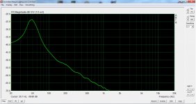
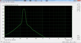
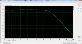
I spent more time with this in the weekend. I believe I have it fully functional now. Indeed it likes the trimmers close to the end of their range but not any further. Attached are frequency response graphs for each mode. Also tested on a linear psu and it was a matter of seconds to tell the transformer from the rectifiers! And it does not react to power cords now.
Regarding shielding, the controls side with the ground plane only asks for grounded potensiometers' bodies and a shield for the rotary switch. Adding a temporary shield to the components side made it to ignore my hand. So, I'm going for a plastic box.
PCB will be updated and released ASAP! Elvee, thank you very much for sharing this!
Attachments

PCB gerber files
Here you are! According to schematic in post #52. I added an LED D10 with its limiting resistor R66 -could be omitted- and a diode D9 to protect for reverse battery connection -it can be replaced with a jumper wire. This diode will drop B+ by 0,7V which is convenient since I used BF245 for J1. Note that silk screen for J1 is for BF256. For BF245 it should be reversed. Finally, the blank PCB serves as a template to drill the holes on the chassis.
Have fun!
Attachments
- Home
- Design & Build
- Equipment & Tools
- An effective weapon for your hum problems: the HumBoy