https://www.diyaudio.com/forums/planars-and-exotics/164414-wave-speakers-4-print.html
The picture here is of the older Gobel panel.
Steve.
The picture here is of the older Gobel panel.
Steve.
Giamesh.
Notice how they have off set the exciter on the round panel in your post.
This helps stop large peaks in the response caused by the round panel edge reflections back to the coil .
This works well.
Steve.
Notice how they have off set the exciter on the round panel in your post.
This helps stop large peaks in the response caused by the round panel edge reflections back to the coil .
This works well.
Steve.
Yes, on a round panel the center would be one of the worst places to put an exciter. I typically use the golden ratio to find where I place them on my panels.
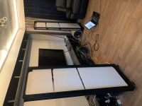
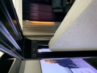
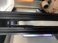
I attach some pictures of my current DML project. I use 3 separate panels with one exciter on each panel for each stereo channel. Sandwiched between two extruded aluminum profiles.
The picture is not up to date, now all 3 panels are of equal size. And there is also a frame around each of the 3 panels.
I have a crossover at 120Hz to my subs
Attachments
Last edited:
I have put the German paper through a different translator which is much better and makes the patent understandable.
4) The panel appears to not be supported at the back and is free-hanging somehow. So no supports on the exciters.
Tsardoz,
Thanks for the updated translation of the patent. I'm eager to read it but must admit I haven't yet. But I'm surprised and a bit skeptical about point 4) above.
On the Gobel website here:
Gobel High End - Ultra High End Speakers and Cables
they make this comment:
The clampings around the bending wave membrane
The clampings around the edges of the membrane consist of various materials (aluminum, rubber, silicon, foam rubber, PU, ...) to ensure an even limitation of the wave through the entire bandwidth. Through this measure, any reflections on the interface to other media are eliminated through the entire bandwidth, which is more than 7 octaves!
Of course, it's possible that the commercial design differs from the patent description, but my guess would be that they are both clamped similarly.
Eric
"The ideal material for mounting an exciter is a thin, lightweight sheet of material with high compressive strength and moderate to high bending strength. The compressive strength of the material has the greatest effect on the treble extension of the resulting ‘speaker’ (affecting ‘detail’ and ‘air’), while the bending strength of the material influences the midrange and low frequency efficiency of the ‘speaker’." From From Dayton website
murry,
Yeah, that's another example of possibly misleading use of terminology.
When they write "strength" they really mean (I hope) "stiffness".
"Strength" concerns a designer only when the forces applied in use either approach or exceed the breaking point or elastic limit of the material in question. And I seriously doubt an exciter can apply such force to any reasonable choice of panel.
"Stiffness" describes the ability of a material to resist deformation at force levels well below the breaking point or elastic limit of the material. Stiffness (not strength) is the property that really influences DML performance.
Eric

It is very long thread. I want to build the canvas art panel made by Spedge and then remade successful by Jaxboy. But I couldn't find the latest best configuration of the art panel.
Could someone help me?
Could someone help me?
OK I have made up a spreadsheet using values from the attached paper.
(download here
Loading Google Sheets)
tsardoz, I admire your effort on the spreadsheet (I have my own similar spreadsheet). But your calculation of the Elastic Modulus of the composite is not correct.
Sorry I can't explain easily the correct equation. But one way to confirm that your equation is wrong is to change the order of the layers. For example, put the Balsa on the outside (0.75 mm each side) and the carbon fiber on the inside (1 mm). For that case you you should get a much lower value for the effective Modulus of the composite. This is because the carbon fiber won't contribute as much to the overall stiffness when it's in the middle as it does when it's on the outside layers.
I think you will find that your equation gives the same result, no matter how the layers are placed. But that's not correct for flexural properties of layered composites. For such composites the flexural stiffness is very highly dependent on the location of the layers. That's why the stiff layers (carbon fiber or fiberglass) are always on the outside, with the less stiff lightweight material in the center core.
If I'm not mistaken, the equation you used does correctly calculate the transverse tensile modulus of a multilayer composite. But that's not what you should be using. What you really need is the equation for the flexural stiffness.
Eric
hansiboy,
I just wrote you a lengthy reply, which somehow got deleted, so here goes, again.
My panels are made from standard canvas 12x16" (or thereabouts) art panels available from Walmart or other bigbox or craft stores. I coated both sides with acrylic paint instead of pva/water, thinned to 30-50:70-50. I used acrylic because I don't like the stark white look, and it allowed me the option to dress up the panels with some color. The mounting pad for the exciter was made from a 4x6 rounded piece of paneling, which I had sanded so that a ply was missing on both sides to make it thinner. It was glued on with full strength pva in the center. I used a Dayton Audio DAEX25FHE-4 exciter from PE that was mounted using the tape glue mounting that comes on them. There is a spline across the back, with a pad of foam between the spline and the exciter. I inserted a 100 mf capacitor between the exciter so the below-50 Hz frequencies are attenuated, as heavy-handed bass songs will make the panels thump, and I like heavy bass. I hung the panels about 3 feet apart (all the space I have) and a foot from a window, with doubled drapes (with 1/2x18x18" melamine panels inserted in the folds) hung between the window and the panels. I was astonished by the sound that comes from these panels. Since I cannot play my system very loud due to my situation here, I augment the panels with a subwoofer and Nautaloss I box speakers to the sides, and XKi box speakers to the rear. I had just built the Nautaloss I and XKi speakers when I stumbled onto this site, and they sound so good that there was no way I was going to relegate them to the closet. Kudos to XRK971 for such great designs!
Last edited:
Refering to the German patent recently discussed:
The back panel (fig.6) which is mentioned with several holes and was mentioned to be some sort of acoustic lens, sparked my curiosity. And after some searching on the web I found this loudspeaker: Ondacustica ultra high-end loudspeakers | Products which also seem to use some sort of bending wave principle together with a back panel at the with holes in it.
What effect would this have on our DML speakers we are discussing in this thread? Could it disperse the sound from the back of the panel and make the panel work as if it further from the back wall then it actually is?
Certainly looks like an "acoustic lens" on the back. I just don't get it if that is the idea.
tsardoz, I admire your effort on the spreadsheet (I have my own similar spreadsheet). But your calculation of the Elastic Modulus of the composite is not correct.
Sorry I can't explain easily the correct equation. But one way to confirm that your equation is wrong is to change the order of the layers. For example, put the Balsa on the outside (0.75 mm each side) and the carbon fiber on the inside (1 mm). For that case you you should get a much lower value for the effective Modulus of the composite. This is because the carbon fiber won't contribute as much to the overall stiffness when it's in the middle as it does when it's on the outside layers.
I think you will find that your equation gives the same result, no matter how the layers are placed. But that's not correct for flexural properties of layered composites. For such composites the flexural stiffness is very highly dependent on the location of the layers. That's why the stiff layers (carbon fiber or fiberglass) are always on the outside, with the less stiff lightweight material in the center core.
If I'm not mistaken, the equation you used does correctly calculate the transverse tensile modulus of a multilayer composite. But that's not what you should be using. What you really need is the equation for the flexural stiffness.
Eric
Thanks I will look into it.
My assumption was composites behaved as rule of mixtures which involves embedded fibres in a composite.
Any suggestions on how to improve it?
EDIT: I will probably test this one day. For example, in double top guitars they have the stiff layer in the middle (nomex) and veneer on the outsides. This is one configuration I was thinking of. Also sandwiched aluminium is similar yet has been reported to be excellent on this forum.
You might well be right but an explanation without some sort of proof or experimental evidence does not convince me either.
EDIT 2: And by your logic the inside layer (inside/middle/outside) contributes nothing. Sorry I am not convinced. If the panel is sufficiently thin (whatever that is, not 1 foot deep for example) I would expect all layers to be interchangeable as my model assumes. As I said I could be wrong.
Last edited:
https://www.diyaudio.com/forums/planars-and-exotics/164414-wave-speakers-4-print.html
The picture here is of the older Gobel panel.
Steve.
That is really interesting and shows end grain balsa with no outer layer but also with the outer incisions.
The outer frame looks similar to the patent but we do not see how the rear side works.
Are these Gobel speakers actually any good? Has anyone heard them?
Rule of Mixtures for transverse loading is Reuss Model (which is what I used in my spreadsheet)
Rule of mixtures - Wikipedia
If anyone can provide data on:
1) layer configuration
2) -3dB point lower limit
I can try it out to see if it works.
As I said I tested it for Gobel's configuration and it predicted the fundamental frequency pretty closely (well good enough). I know it is not perfect but it suggests the configuration I was thinking of (CF/nomex/CF) won't work well at all with fc something like 500-600 Hz for a small panel. Small panels need softer materials for bass extension like the Gobel one does.
If this formula/spreadsheet works it can save a lot of wasted trial and error.
Last edited:
So the spreadsheet works close enough for the Gobel construction and dimensions which has CF-balsa-CF where the crossover point is 170 Hz and I estimated -3dB to be around 140 Hz. This is close.
Let's try an acoustic guitar double top which has a soundboard are of about 0.15 square metres. These are configured the opposite of Gobel with spruce/nomex/spruce (0.7/2/0.7mm). According to Veleric this formula should not work as the order is different with stiff in the middle rather than on the outsides.
My spreadsheet estimates this to have an fc about 150Hz. Changing to a softer wood would decrease this by some degree. Note that woods have about 1/4 the Young's modulus across the grain as with the grain so this also needs to be taken into account (I took the average of the two).
Anyway the lowest note on a guitar is about 83 Hz. This is still ballpark of 150 Hz. Maybe they do not use spruce but something else which is softer.
Anyway as I said CF/nomex/CF in a small panel of similar size predicts 400 Hz or so tells me straight away not to bother.
This is not intended to be super accurate but is better than a random guess.
Last edited:
Let's try an acoustic guitar double top which has a soundboard are of about 0.15 square metres. These are configured the opposite of Gobel with spruce/nomex/spruce (0.7/2/0.7mm). According to Veleric this formula should not work as the order is different with stiff in the middle rather than on the outsides.
I think the double-top idea has merit. I first learned about double-top guitars on this thread! I tried it myself already with walnut/nomex/walnut. But my execution was poor so it didn't turn out as good as I think it could have. Hopefully you will do a better job of it than I did.
My biggest mistake was to use Titebond (PVA) wood glue between the veneer and the nomex. The water-based PVA saturated and warped the veneer so it was hard to glue it properly to the nomex. I should have known better. Epoxy or PU glue would probably have been a better choice.
The spruce/nomex/spruce is actually a typical composite layup with the stiff stuff (spruce in this case) on the outside and the lightweight/compliant layer (nomex) in the core.
Eric
Thanks I will look into it.
My assumption was composites behaved as rule of mixtures which involves embedded fibres in a composite.
Any suggestions on how to improve it?
In pure tension, multilayer composites may in fact behave like fibers embedded in a matrix. But for flexure, they do not. (Not even close, in fact).
I've been looking for a good link to help you out, and I think this one is it:
Sandwich theory - Wikipedia
Look for the equations for D. This is the parameter you need for the calculation of Fc and F0, etc.
There are several expressions for D on this page, depending on what simplifying assumptions are valid. The most simple of these is:
D=2Efh(f+h)
where E is the modulus of the outer skins, f is the thickness of each skin layer and 2h is the thickness of the core.
Note, this particular equation assumes that the outer skin modulus is much thicker than that of the core, and the skin thickness is much less than the core thickness.
There are other approximations shown depending on what approximations are valid.
Just beyond halfway down the page for the equation in the box that starts:
Dbeam=
If you want to try that one, for the parameter C11face, use the elastic modulus of the outer layers.
You should be using one of these expressions (or similar expression derived for flexural bending) for determining the value for stiffness (D) to use in your speaker plate calculations, rather than the rule of mixtures formula, which simply doesn't apply to flexural stiffness of a plate.
I hope you find this helpful.
Eric
Now check the German patent design...
Young's Modulus (Gpa) thickness (mm) density (kg/m^3) volume fraction Material Notes
Layer 1 80 0.5 1500 0.2 carbon fibre
Layer 2 3.71 1.5 150 0.6 end balsa
Layer 3 80 0.5 1500 0.2 carbon fibre
Help me here: which patent did this come from? In the Gobel patent (paragraphs 55-57) I see referenced 1.5 mm balsa and 58 g/m2 fiberglass, which would normally be under 0.1 mm thick: so not not carbon fiber and not 0.5 mm thick. Which German patent are you referring to here?
Eric
Tsardoz.
My point about panel damping is that it will usually alter the sound and not necessarily in a good way.
It may give you a flatter frequency response but at what cost ?
I usually use other methods which I have described on this site , to sort out these problems.
Indeed, what cost? Every reliable source I have read suggests that adding perimeter restraint and/or damping provides only improved performance. No reliable source I can recall ever mentioned a negative (i.e cost) result as a result of perimeter restraint or damping. What are the costs that you perceive?
I usually try to increase the panel performance in a good way , and not to reduce it.
My understanding is that damping indeed reduces both constructive interference (which causes peaks) and destructive interference (which causes dips). But that seems more like a benefit, rather than a cost, no?
Eric
There are several expressions for D on this page, depending on what simplifying assumptions are valid. The most simple of these is:
D=2Efh(f+h)
where E is the modulus of the outer skins, f is the thickness of each skin layer and 2h is the thickness of the core.
Note, this particular equation assumes that the outer skin modulus is much thicker than that of the core, and the skin thickness is much less than the core thickness.
I went back to look at the equation I used in my own spreadsheet, and realized it was not as complicated an expression as I was thinking earlier. What I used was this:
D= (2/3)(E1)f^3+(2/3)(E2)h^3+2(E1)fh(f+h)
where E1 is the elastic modulus of the skin(i.e. face) layers and E2 is the elastic modulus of the core layer. Also, t is the face thickness and 2h (yes 2h, not just h) is the core thickness.
if I've typed correctly, this matches the first (least simplified) equation in the wiki link I shared earlier.
Sandwich theory - Wikipedia
tsardoz should like this one better, because it includes the contribution of the core layer stiffness. Often the contribution of the core layer is minimal, but sometimes not, especially if the core is wood (rather than say, foam or nomex), and also if the face layers are really thin compared to the core. So it's best to include it in the calculation, since it's just a little more typing.
Eric
- Home
- Loudspeakers
- Full Range
- A Study of DMLs as a Full Range Speaker