My design with Magnetics mpp cores, and onsemi sic devices. No active clamp , single switch flyback.
For ev. Charger or class td or classd amps
10kw flyback with %95 efficent - YouTube
For ev. Charger or class td or classd amps
10kw flyback with %95 efficent - YouTube
Last edited:
I think you will reach a lot more people if you can give an English description on the Youtube.
Jan
Jan
I think you will reach a lot more people if you can give an English description on the Youtube.
Jan
Agree.
Suggest you *at least* add English subtitles to YT and even better post a Bilingual page (Turkish/English) with the full project, including schematic, PCB if available, some measurements, etc.
Or post such page here.
The project certainly has merit.
Hi sirI think you will reach a lot more people if you can give an English description on the Youtube.
Jan
I don't speak english well enough, sory
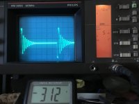
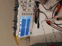
Hi dorel this video for youSome pictures with the oscilloscope in the mosfet drain?
flyback drain scope for diyaudio - YouTube
Hello Veysel;
Very nice flyback. Can i ask for switching frequency? I am working on LLC. I watch your magnetic selection tutorial on youtube. It is very fine thanks. I am planing to use TDK N87 or N97 CORE toroid for main transformer. But i am not selected the resonant tank inductor yet. Do you have any material suggestion for the LLC inductor?
Very nice flyback. Can i ask for switching frequency? I am working on LLC. I watch your magnetic selection tutorial on youtube. It is very fine thanks. I am planing to use TDK N87 or N97 CORE toroid for main transformer. But i am not selected the resonant tank inductor yet. Do you have any material suggestion for the LLC inductor?
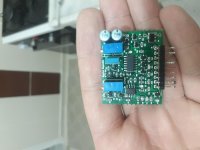
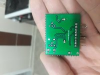
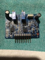
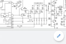
Hi dorel my pwm this , same differents from pwmf1 (Kenneth Andersson design)
Attachments
Last edited:
Hi potstipHello Veysel;
Very nice flyback. Can i ask for switching frequency? I am working on LLC. I watch your magnetic selection tutorial on youtube. It is very fine thanks. I am planing to use TDK N87 or N97 CORE toroid for main transformer. But i am not selected the resonant tank inductor yet. Do you have any material suggestion for the LLC inductor?
Thank you for your opinions.
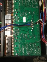
This flyback 22khz light loads , linearly incrased 40khz at full power , and unlock duty cycle limit at high power.
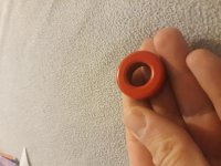
For llc inductor 2 material best (example t106-2)
But new designs not use llc coil , new designs use small gap for leakage inductance and differerent winding (for maximize leakage inductance)
Attachments

Hi sir
I don't speak english well enough, sory
Hi Veysel ... you can solve that with patience 🙂
Start by writing your description and translating it with Google translate, then you add subtitles.
In have gotten very good results by following a basic rule:do NOT use "slang" or "trade words" , etc., only what is available in a standard dictionary.
Translate is a dumb computer program, not a Human, and you must "help" it.
So no "amp" , "XFormer", "pot", "cap" "OT", etc. but
* Amplifier or Ampere
* transformer
* potentiometer
* capacitor
*output transformer
etc., and results will be much better, guaranteed, then you add subtitles to your video.
Same with any descriptive post here.
And in any case, schematics and PCBs are "universal" 🙂
Scope images and closeup pictures too 🙂
D*mn Covid , I would NOW be crisscrossing the Bosphorus in one of those white ships (do they still exist?), sipping best coffee or tea or refreshing Ayran, eating that multi flavoured ice cream in a freshly made still warm cone or a grilled fish sandwich, at the side of the fishing boat 😀 😀 😀
Oh well 🙁
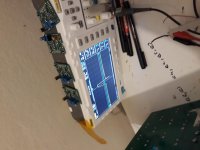
I think it's the same only that yours is a double integrated.I have two prototypes, one with ka7552, ee70, 5kw and one with pwmf1 with pm87 of 8-10kw.The picture with the oscilloscope is with minimal consumption.
Attachments
Last edited by a moderator:
Thank you ı will tryHi Veysel ... you can solve that with patience 🙂
Start by writing your description and translating it with Google translate, then you add subtitles.
In have gotten very good results by following a basic rule:do NOT use "slang" or "trade words" , etc., only what is available in a standard dictionary.
Translate is a dumb computer program, not a Human, and you must "help" it.
So no "amp" , "XFormer", "pot", "cap" "OT", etc. but
* Amplifier or Ampere
* transformer
* potentiometer
* capacitor
*output transformer
etc., and results will be much better, guaranteed, then you add subtitles to your video.
Same with any descriptive post here.
And in any case, schematics and PCBs are "universal" 🙂
Scope images and closeup pictures too 🙂
D*mn Covid , I would NOW be crisscrossing the Bosphorus in one of those white ships (do they still exist?), sipping best coffee or tea or refreshing Ayran, eating that multi flavoured ice cream in a freshly made still warm cone or a grilled fish sandwich, at the side of the fishing boat 😀 😀 😀
Oh well 🙁
Frequency approx.27khz constant at low and full power.The picture above is with ka7552.
Last edited by a moderator:
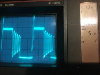
How to eliminate sawtooth signal ?
Hi all
This scope screens from gate drain (no load and 1kw load)
How to eliminate sawtooth signal ?
Hi all
This scope screens from gate drain (no load and 1kw load)
How to eliminate sawtooth signal ?
Attachments
Last edited:
Hi,which is the maximum power you managed to get out of smps?I took two 2500w / 4ohm Labgruppen amplifiers in clip to 2x150v ee70 power supply.
I can't test the maximum power in a home environment, it can be dangerous, I use mpp core theoretically, it can give 4 times the power of pm87, current limitation cuts it at rms 5kw. Orginal labgruppen effiency %88 , my design %94.
Can you show me ee70 in case
Last edited:
youtu.be/oQeERmYjE4I Only 1 Labgruppen amplifier.Something is wrong with the drain signal. I used igbt and silicon diodes, silicon carbide diodes are not good they have too much capacity.Is the oscilloscope secondary to the negative branch?
Last edited by a moderator:
- Home
- Amplifiers
- Power Supplies
- 10kw flyback with %95 efficent