Thanks. The rectifier bridge ground lifter comes from this article on ground loops (start on page 23): http://hifisonix.com/wordpress/wp-content/uploads/2019/02/Ground-Loops.pdf
That is quite an interesting read. I've not dealt with many ground loop problems; but I'm saving this PDF link. Thx.
Having offset problems...
Status: all rails are good, amp turns on as expected, bias is adjustable.
The offset pots are having no effect (both channels). I've measured them and they change resistance as expected. I've measured the resistors close to them and they're all within spec. Any idea what's going on? What I can check? Is there something easy I can look for before pulling transistors off the boards? Thanks!
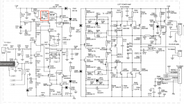
The circuit around them:
Status: all rails are good, amp turns on as expected, bias is adjustable.
The offset pots are having no effect (both channels). I've measured them and they change resistance as expected. I've measured the resistors close to them and they're all within spec. Any idea what's going on? What I can check? Is there something easy I can look for before pulling transistors off the boards? Thanks!
The circuit around them:
Attachments

Just being certain: no speakers connected and amp is on for at least 10 minutes, all controls flat, no input source.
Check:
- Q308 + Q312 (shorts, opens)?
- Zeners D301 + D302 (are these holding at 18V reference)
- 1N4148 (D303, D304, D305, D306) shorts?
- Q305 (short, open)
Just some quickies than can be checked.
Check:
- Q308 + Q312 (shorts, opens)?
- Zeners D301 + D302 (are these holding at 18V reference)
- 1N4148 (D303, D304, D305, D306) shorts?
- Q305 (short, open)
Just some quickies than can be checked.
Just being certain: no speakers connected and amp is on for at least 10 minutes, all controls flat, no input source.
Correct.
Check:
- Q308 + Q312 (shorts, opens)?
- Zeners D301 + D302 (are these holding at 18V reference)
- 1N4148 (D303, D304, D305, D306) shorts?
- Q305 (short, open)
Just some quickies than can be checked.
Thanks, will check these.
If one channel is within specification for dc offset then some measurements can be taken for cross reference with the one that is not.
It would be helpful to know the specific voltages of the dc offset whether negative, positive or variable within both ranges.
I suggest measuring the voltages at the bases of Q309 and Q312 in the circuit diagram provided if this is the channel with the discrepancy and compare these with the same parts in the one that is within specification. Hopefully Q312 will match with the partner in the other channel.
Q305 is configured as a base emitter diode and the resistance of VR301 and R307 is 100R+980R which matches R321 in the negative half of the circuit.
Q309 is a PNP type so adjusting at 1k total resistance of the adjustment the base voltage will change the voltage at the base of Q309.
The closer this is to the emitter voltage which is fixed in this instance the less current it will pass.
With regard to measuring voltages the safest and most accurate way to do this is to do this with respect to earth. The black output terminal is connected to earth which makes it possible to put the black probe into this outlet and use the the red to measure. The voltage difference between two points being measured is simple arithmetic.
I expect whichever State you are living in would have their electrical wiring regulations online.
No. And it is a long explanation.
Electric regs were first posted by cities: Boston, Chicago, NYC. More and more, all different, and impacting fire insurance costs. (Remember the codes protect the insurers, not really you.) A group formed and about 108 years ago the first "National Electric Code" was published. This is a "model code", NOT The Law.
More recently "most" towns and cities adopted the NEC with local addendums. (Even more recently my State is trying to require NEC in towns which have not adopted any code, and in the rather large woods outside of any city/town borders.) My town uses an old (2015?) NEC. The town next over has extra requirements (that town burned several times so they are conservative). Chicago (Mrs. O'Leary's cow) has usually required full conduit almost everywhere.
You PAY to own the NEC. Couple hundred $ to have the latest edition. (There are cheaper "commentaries" which cite most of the good parts to explain them.)
The NEC has little or nothing to say about INSIDE the appliance (amplifier). That has been the realm of UL, another insurer protection committee. Their requirements are very detailed and they $ELL them by-by-the-section. UL had a near-monopoly because nobody else wanted the job; as UL's rates went up and markets globalized there are now many "recognized labs" who participate in setting standard and testing products to those standards.
Canada's rules are similar but mostly a little more sane (less OCD).
> if I wanted to add a safety earth/ground to the amp
With the large exception of Vintage Stage Amps, I feel that a commercial product already tested to UL/etc should NOT have its grounding messed-with. For "hum/buzz" it is far more important that all the components (phono, preamp, power amp) are bonded to each other, than to utility common or outside dirt. If it was approved safe in 1970, it is probably safe today. If it was safe in 1950, the rubber is probably rotted; respectfully replace the cord just as it was. (Both sides potentially "hot".)
Last edited:
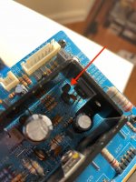
Hmmm the way everything is laid out, I can barely get probes to some components with amp modules on my desk. Some of the transistors are impossible to probe. Basically there's no way I can think of to take measurements with everything installed and plugged in in the chassis. I have one of these el cheapo testers https://smile.amazon.com/dp/B07WT9VVZB?psc=1&ref=ppx_yo2_dt_b_product_details so I'll take the boards off the heatsinks and start pulling components. Thanks guys.
Hmmm the way everything is laid out, I can barely get probes to some components with amp modules on my desk. Some of the transistors are impossible to probe. Basically there's no way I can think of to take measurements with everything installed and plugged in in the chassis. I have one of these el cheapo testers https://smile.amazon.com/dp/B07WT9VVZB?psc=1&ref=ppx_yo2_dt_b_product_details so I'll take the boards off the heatsinks and start pulling components. Thanks guys.
OK, that is an el cheapo meter. 🙂
So you can check without power. Sure resistances may not be accurate, but device shorts will showup (diode mode).
I try and check as much as possible without power applied. Plus it's safer than a probe slipping with power applied.
Also, as one poster states, you have a decent channel to compare to.
Also, as one poster states, you have a decent channel to compare to.
The problem is the decent channel doesn't respond to pot changes either

Hmmm the way everything is laid out, I can barely get probes to some components with amp modules on my desk. Some of the transistors are impossible to probe. Basically there's no way I can think of to take measurements with everything installed and plugged in in the chassis. I have one of these el cheapo testers https://smile.amazon.com/dp/B07WT9VVZB?psc=1&ref=ppx_yo2_dt_b_product_details so I'll take the boards off the heatsinks and start pulling components. Thanks guys.
You don't need to take a blanket approach with other components like you did with your recap. Faults can be detected by following processes.
Forget for the time being there is no change in dc voltage from moving the trimpot and do the measurements for the few points I suggested. That should should help narrow the focus.
just curious, if you remove the pre-out/main-in RCA jumpers and retest; is the DC offset still high and un-adjustable?
just curious, if you remove the pre-out/main-in RCA jumpers and retest; is the DC offset still high and un-adjustable?
All my testing is done with the preamp out of the circuit (jumpers removed) and shorting plugs on the main-in/amp input.
You don't need to take a blanket approach with other components like you did with your recap. Faults can be detected by following processes.
Forget for the time being there is no change in dc voltage from moving the trimpot and do the measurements for the few points I suggested. That should should help narrow the focus.
Ok, will do thanks.
.....shorting plugs on the main-in/amp input.
I'm not understanding, shorted to what?
do the measurements for the few points I suggested.
So here's the issue with that - I can't get a test lead or anything else to Q312 (and most of the others as well) due to their physical location to measure voltage. I literally have to take them off the board. So that's what I'll be doing...sigh...
Attachments
I'm not understanding, shorted to what?
hmm, well I searched and I understand now. I never used these. Although I could see these coming in handy to debug a ground plane issue.
Hmmm the way everything is laid out, I can barely get probes to some components with amp modules on my desk. Some of the transistors are impossible to probe. Basically there's no way I can think of to take measurements with everything installed and plugged in in the chassis. I have one of these el cheapo testers https://smile.amazon.com/dp/B07WT9VVZB?psc=1&ref=ppx_yo2_dt_b_product_details so I'll take the boards off the heatsinks and start pulling components. Thanks guys.
If the modules are on your desk where is the connection to earth. You need to have this so capacitors C303 and C304 bypass zener noise due to diodes D301 and D302. If there is zener noise in the input set up it will be amplified.
You have measured 400 m.v. a.c. at the output of the faulty channel. Also if the modules are not inside the case there is no shielding against radiated h.f, noise in the ether or by the power transformer in combination with diodes in the rectifier bridge switching on and off in the process of charging the capacitor bank.
If you put everything back into the chassis and connect the earth system you might find the shielding and effective earthing will make a difference.
- Home
- Amplifiers
- Solid State
- NAD C370 help pls