There is an art to soldering which takes a while to get right.
Since we have youtube demonstrations on any subject you can name I will leave that of soldering for others to research.
Actually any NAD chassis is an excellent practice item. 🙂
Seriously.
And sadly, leaded solder works better over non-leaded.
There is an art to soldering which takes a while to get right.
Since we have youtube demonstrations on any subject you can name I will leave that of soldering for others to research.
The excessive flux is from the factory not me lol.
The excessive flux is from the factory not me lol.
I don't think @mjona was implying this.
In my small experience of NAD QC, this is the norm.
And the end users / owners / service-techs / hobbyists are left cleaning up the leftovers. 😀
The reward is a wonderful sounding piece of audio equipment.
I don't think @mjona was implying this.
I didn't think so lol just wanted to clarify just in case. I'm no EE but my soldering A+++
The excessive flux is from the factory not me lol.
It was not the excessive flux - that is easy to deal with using a propriety cleaner.
A good solder joint should have a shiny silver appearance. Over time metals suffer from oxidation and moisture in the air which dulls their appearance. They also expand and contract according to the levels of heat.
On how to deal with possible miscreants, it was easier for me to suggest accessing resources on youtube where along with the commentary one can see how things are done.
I am sorry if I came across too short - I had to attend a funeral for my sister in law this morning.
@mjona
Hopefully today is a better day. It's always terrible losing a family member.
@A Jedi
I keep looking at that PCB foil side and just want to go over all the solder pads.🙂
Not sure about the white/light color stains.....could be possible water stain from the past??
I've spent a lot of time with an eye-loop / magnifying glass inspecting solder pads that I just make it part of the ritual of solid state amp repair.
OK, it just looks bad in the pic. Just be certain there's no "wiggle" when pushing on the resistor lead. FWIW, I'll remove all solder then reapply with 60/40 on a difficult joint.
There are 2 joints below the screw head that also have the "look" of a bullseye or broken joint.
Ok, I'll review all the joints and reflow anything questionable I see. I've looked the boards over with a magnifying glass but I'll go through them again.
It was not the excessive flux - that is easy to deal with using a propriety cleaner.
A good solder joint should have a shiny silver appearance. Over time metals suffer from oxidation and moisture in the air which dulls their appearance. They also expand and contract according to the levels of heat.
On how to deal with possible miscreants, it was easier for me to suggest accessing resources on youtube where along with the commentary one can see how things are done.
I am sorry if I came across too short - I had to attend a funeral for my sister in law this morning.
I'm sorry for your loss 🙁
No, you weren't too short - you don't know me and you're trying to be helpful. Nothing wrong with that. Perhaps I was being too defensive. Thanks for all you help!
Not sure about the white/light color stains.....could be possible water stain from the past??
I
Yeah the light colored stains are ones that I'm not sure how to explain? The amp has always been treated well and never seen a drop of water. Some sort of residue from the solder bath? Or some process afterwards? Anyway, I'll remove the stuff and that'll be that.
It might be possible to get away with heating some of the solder to get it to flow and reset. It could be the iron was not hot enough or applied too quickly by a factory worker.
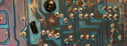
The solder joins should have a silver sheen like a number on the right hand side of the image attached.
Some have a dull finish - example circled in blue and others have the form of a blob - examples circled in red.
One cannot tell what is going on under the surface with the latter and to find any rogues among these blobs a process of elimination is the best method.
For the blobs the solder needs to be removed using a suction tool and the component lead wires cleaned up so the surfaces will take fresh solder.
A fine grade of abrasive paper or a sharp knife used as a scraper - with a damp rag and paper tissue to mop up would be my suggestion using your best judgment with your approach in these regards.
Attachments
Hello lovely people. An update and a question.
Amp powers up, all PSU voltages are good.
Due to a few suspect diode readings on the amp boards, I went ahead and changed ALL diodes on the boards. Now I have 1 fully working channel (yay!). I can set offset and bias without problems.
The other channel still has an issue somewhere though as I am unable to influence offset via the pot. The pot itself is functioning properly (I've measured it). The resistors, caps, diodes measure identically to those on the working channel. When turning the amp on, DC offset starts out ~4mv and slowly but steadily starts rising as the amp warms up. Within about a minute it's up to 80mv and still rising. At this point I just shut it off.
So, I'll be pulling devices off the board and measuring them.
My question has to do with the fact that all these devices are out of production. There are new substitutes but I am far from an EE so I have no idea how to choose the best replacement or if it really matters based on the location of these devices on the board (maybe they have no influence on the audio signal?).
I assume the fault lies with one of the highlighted devices (the VR is green):
- Home
- Amplifiers
- Solid State
- NAD C370 help pls