I have boards I could send for postage. They are dacz layout and I’ve built them up so I know they work.
Those look great! I'll take a pair. PayPal ok?
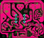
I received the boards today! Thank you Evan. Quick question.. whats the best way to mount the output transistors to the heat sink? I'll look back on the thread to see what I can find. As these are centrally located more or less.
Hi everyone. It is a very long and interesting thread, but it can be daunting for new comers. I compiled most of the interesting comments to help potential builders. It can be of some use to others... It is more or less up to date.
I know I'm way late to the party, and all of the helpful links are now in antiquity, I was wondering how bad off I would be if I used a ceramic cap for C5 instead of silver Mica? Must be a good reason mica is specified. My eyes are crossed from searching..
Compensation.......
Hi 2pist,
Silver micas are selected for very high frequency performance. Here's the reason.
Any global feedback amplifier must be compensated so it will not oscillate. This can happen when phase shift from front to back of the amplifier approaches 180 degrees, transforming negative fb into positive fb. This usually destroys the output stage of the amplifier, and often the speaker drivers, so it must be avoided at any cost. The trick is to drop the loop gain to below unity; if it is less than unity loop gain, positive feedback will not accelerate the input of the amp towards oscillation.
On a SS amplifier this Unity Loop Gain Frequency (ULGF) happens around 500KHz to about one MHz, depending on the design and components. To reduce the loop gain (the 'excess' gain over the nominal 'closed' gain set by the fb resistive divider) we use a small cap from the voltage amplifier down to its input, or even the fb node. Usually this cap is strung between collector and base of the VAS. The cap must be temperature and frequency stable, and so we use silver mica. You can use COG and NPO ceramics, but I generally find the sound seems to be a bit better with silver mica.
Books are written on compensating feedback amplifiers. It is a category of electronics called 'control theory' and applies to any device set up for gain using negative feedback. Control theory even applies to sugar levels in the human body, for example, it is ubiquitous.
Cheers,
Hugh
Last edited:
Thank you for the input Hugh. I found a pair of 48pf micas I will try. I made a few substitutions, like a TTC0002 with a Irf240. I had to increase VR1 to 1k to get the offset closer, but that in turn increased the bias to .7 volts. It's a current hog, closest thing to class A I ever put ttogether.. Math isn't my strong suit. I still think I can trial and error my way to success. Good thing it's just a hobby for me, but I always try the parts I have on hand to see if I can cobble together something reasonable.
I could use a little help.. I can not get the offset below 260 MV. I used a green led and it's dropping 2.3 volts. I think it should be closer to the equivelent of the 2 diodes it replaces? Or 2.9 volts?
2pist,
Most leds drop around 1.95V at 3mA.
Your led might be out of tolerance, but in this circuit the excessive drop across your led corresponds to your higher offset.
Try another green led, see what happens. Failing that, go back to two diodes.
Cheers,
Hugh
Most leds drop around 1.95V at 3mA.
Your led might be out of tolerance, but in this circuit the excessive drop across your led corresponds to your higher offset.
Try another green led, see what happens. Failing that, go back to two diodes.
Cheers,
Hugh
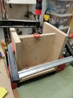
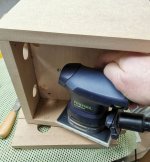
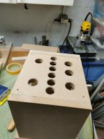
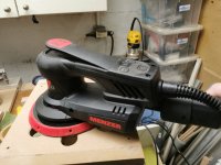
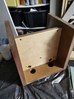
Some more work on chassis : gluing the second chassis, some sanding with my two favorite two sanding machine. The RTS 400 EQ for small area, and the Menzer ETS 150 2.5 for bigger. I apply one layer 2K epoxy resine on first chassis. I hope it will dry coorectly as it is a hold stock one. I order some new
Attachments
I could use a little help..
Sorry I haven’t seen this sooner.
As Hugh said you need a lower voltage drop on the green led.
For mounting I believe Dacz plan was to pinch the output transistor between the board and heat sink. I ended up drilling the mounting holes in the board bigger and mounting the transistors with Allen head bolts that fit through the enlarged holes in the board
Some more work on chassis : gluing the second chassis, some sanding with my two favorite two sanding machine. The RTS 400 EQ for small area, and the Menzer ETS 150 2.5 for bigger. I apply one layer 2K epoxy resine on first chassis. I hope it will dry coorectly as it is a hold stock one. I order some new
can't wait to see the rest
Sorry I haven’t seen this sooner.
As Hugh said you need a lower voltage drop on the green led.
For mounting I believe Dacz plan was to pinch the output transistor between the board and heat sink. I ended up drilling the mounting holes in the board bigger and mounting the transistors with Allen head bolts that fit through the enlarged holes in the board
No worries. You guys are awesome. I'm waiting on one Irfp240 to finish my second board. I'm using these in a car amp I built like 15 years ago. I figured out a way to mount them to the case. (Made from aluminum I beams) the smps design is from an old Orion amp I reverse engineered when I was young enough to do such a thing. Lol. And it's going to power a system for my handicapped daughter. It runs at 44 volts per side. I would upload some pics but it looks like they need to be hosted off site.?
44V rails will give you good power; I would estimate from your setup around 90W into 8R, and probably quite a bit more into 4R, the usual impedance for auto speakers.
A car is a noisy environment and even a noisy amp would not be noticed over the road noise and running gear. But the VSQA has a high level of second harmonic conferring a slight 'warm' sound which is immediately noticed even in a car interior. The use of a mosfet one side and bipolar on the other in the output stage enhances this 'warmth' and many people like it. It tends to relax and calm, which is precisely what you need in a car, particularly in traffic!! In fact I have an old car with a Mark Levinson sound system and I'm expecting it to fail, they have a bad reputation. I will use the VSQA to replace it when it inevitably goes to God........
I always liked Thiago's and PHunk's pcbs. Wonderful! This amp was very popular and easy to get running. I hope your daughter loves it too!
Hugh
I'm happy there are people on this earth like you Hugh. And everyone else that positively adds to this community.
I might should start a new thread with this question, but what kind of solder and Flux do you all use? I had a big roll of RadioShack solder and Flux I recently ran out of. I bought some crap on Amazon that is garbage. Regardless of the Flux I use it is dirty and Grey. Headers break lose as soon as you plug one up. I chased bad solders all over the last boards I built using the junk.
There must be a quality solder with no clean Flux out there. I'm apprehensive of using acidic Flux as I destroyed 8 output fets using a spray cleaner once.
How do you clean your boards?
Hi 2pist,
thank you for your nice comments.....
Solder:
I use Ersin Multicore, and it is 60/38/2 in lead/tin/silver. It's a low temp solder with integrated rosin, diameter is 0.71mm. There is a company in Australia, Consolidated Alloys in Melbourne, who make a similar solder, though not quite as good, who I buy from recently. If you can avoid no lead solder you will find your work is much easier. I think Kester in the US market make one with lead; I'm not sure. But it's hard to make an easy working solder without lead.
Cleaning:
Use water and steel wool (an Oz version of your scouring pads). You can use an abrasive paste if its bad, but generally the Cu layer is thin and too much abrasion is not good as it might lift the track later during soldering.
Hugh
- Home
- Amplifiers
- Solid State
- Very simple quasi complimentary MOSFET amplifier