who knows, maybe 50C of the chip temperature just compensates 3rd harmonic of my FDA.
Don't really believe but I see some chance.
Don't really believe but I see some chance.
ES9038Q2M
I've bought 3 ES9038Q2M chips from Mouser on different occasions. Yesterday when I was about to populate my DAC board I noticed that 2 of the chips have the "mousebite" on the wrong corner. I.e. the dot on the top side and the mousebite on the bottom are on different corners. I don't know how common this is within the industry but first time I've seen such. QC at ESS apparently needs improving.
I've bought 3 ES9038Q2M chips from Mouser on different occasions. Yesterday when I was about to populate my DAC board I noticed that 2 of the chips have the "mousebite" on the wrong corner. I.e. the dot on the top side and the mousebite on the bottom are on different corners. I don't know how common this is within the industry but first time I've seen such. QC at ESS apparently needs improving.
That's a first, never heard about something like this. I would send them back to Mouser and file a complaint with ESS. It's a much bigger thing than poor QC.
I don't know how common this is within the industry but first time I've seen such. QC at ESS apparently needs improving.
I've had production of thousands(about 5000) DACs 9038Q2M based and no one was upturned on the PCBA i.e. just pick&placed from the reel and all 100.0% chips were soldered in the correct position/direction. Also, I didn't see the top marking text upturned at the PCBA. Hence, your case is rather unique.
The 2 chips with misplaced mousebite are from the same batch so I assume all chips from that reel have the same issue. The dot on top is correctly placed.
I have made a support request to ESS but not a complaint. Let's see if they will even answer to my support request.
I have made a support request to ESS but not a complaint. Let's see if they will even answer to my support request.
How do you know the dot shows pin 1 and not the mouse bite?
Knowing a little about IC assembly, I would think this would be an extremely unlikely situation. Attempting to wire bond a chip wrongly placed on the frame is very hard to imagine, the automatic bonding machines would not find the connection pads in the expected position.
The dot is usually laser marked after the chips are assembled, moulded and the final test is completed. I can see a possible (but very unlikely) error there, if the feed is reversed.
If the mousebite is correct every design made so far would have to scrapped 😀
The mousebite in the "faulty" chips is on the top right corner instead of the lower right corner (see datasheet p.60).
The mousebite in the "faulty" chips is on the top right corner instead of the lower right corner (see datasheet p.60).
That's even weirder, so it is a mirroring error not a rotation error. Who knows, but if you ever find the problem root cause let me know.
I got a response from ESS for my support request stating that the dot marking is correct. They also stated that ESS product engineer will contact their IC assembly house to correct the error.
So the root cause will remain hidden. Could it be that ESS is still running "homespun" processes.
So the root cause will remain hidden. Could it be that ESS is still running "homespun" processes.
Nice to get access to the datasheets without an NDA. And it seems like a lot of information has been added compared to the one I got under NDA.
Coming back to the DAC for a moment.
Long time ago I made some measurements and experiments on a low cost DAC board with ES9038Q2M, see ES9038Q2M Board
As the measurements show, I was not able to get better THD at 1 kHz than around -103dB at 0dBFS. I have just measured again at -1dBFS, where I get around -105dB.
I would like to hear from members here, who have experience with the ES9038Q2M: Is this what can be expected without THD compensation or is there something that must be changed to improve it?
I would like to get a reasonable performance before making my own board, with improved low noise and low impedance supply etc.
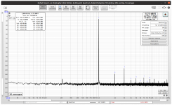
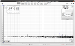
Here is my ES9038Q2M board without/with THD compensation. This is using one of the chips that has incorrect mousebite. The DAC output is at -1dBFS but I used my Autoranger to lower the output to -6dBFS which helps to hide the ADC distortion (AK5394). THD is closer to datasheet but THD+N is still quite far but that is partly related to using Autoranger to lower the gain.
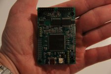
BTW I'm now using my STM32F7 USBI2S bridge for both DAC and ADC although not yet in synchronized mode. The new USBI2S board has the DAC clocks outside of the isolator to be more compliant with the demands of the jitterati. More importantly I've also added two 5+1 isolators for isolated I2C and GPIO (2 for DAC and 4 for ADC). So now I'm able to use the same STM32F7 as both USBI2S bridge as well as MCU for DAC and ADC boards (or other stuff).
Attachments
Here is the new incarnation of my STM32F723 USBI2S bridge. The size of the board remains the same (75x50mm). The I2S isolators are MAX14435F and the secondary isolators (I2C and GPIO) are SI8661.
For I2C isolation I used this:
https://www.ti.com/lit/an/slyt403a/slyt403a.pdf?ts=1636225345420&ref_url=https%253A%252F%252Fwww.google.com%252F
Although it looks sketchy with obscure resistances it actually works even with obtainable resistor values both in standard and fast mode with both AKM and ESS chips. However 2+1 (out, in) channels are needed as SDA needs to be bidirectional.
In case it is not obvious the purpose of this USBI2s bridge is to be used as a combined USBI2S bridge and MCU for testing DAC and ADC boards. Of course it can be used to implement USB audio DACs as well.
Attachments
Why do you need two i2c interfaces?
Don’t you need to somehow sync the CLK_OUT with the LRCK and BCK? Or are both i2s in and out interfaces assuming the da and ad in master mode?
Don’t you need to somehow sync the CLK_OUT with the LRCK and BCK? Or are both i2s in and out interfaces assuming the da and ad in master mode?
To continue my monologue here is the schematic of the USB2I2S board.
Have you measured power consumption at all? Looks good, btw.
Why do you need two i2c interfaces?
Originally I had both I2S_out and I2S_in using the same I2C and used another I2C for e.g. OLED-displays. In the new board I just wanted to add some flexibility (probably not needed). Also using separate I2C interfaces helped the somewhat crowded layout (4-layer board).
Don’t you need to somehow sync the CLK_OUT with the LRCK and BCK? Or are both i2s in and out interfaces assuming the da and ad in master mode?
DAC is in slave mode. ADC in master mode.
The LRCK and BCK for I2S out are generated by the MCU from CLK which is also used for CLK_OUT. There may be some additional propagation delay in LRCK and BCK but so far I have not seen any problems (at least for 192k/32).
Have you measured power consumption at all? Looks good, btw.
Measured with DVM from USB VBUS the current is about 130mA both at idle and when streaming 192k/32 out+in.
Hello bohrok2610,
I discover your work on this USB-I2S board, congrats !
Can you tell us more about it's specs?
Does it have several IN/OUT channels ?
What sampling rate are supported ?
Does it require audio drivers ? 5 (Linux/Windows compatibility)
Is your design is based on the SDR-widget ?
Your board seem to work as USB / MCH streamer board from miniDSP, right ?
Do you plane to make you design available in any way? (or open source?)
One thing would we great and are missing from other USB-I2S adapter is the ability to use it
as slave, with an external MCLK source.
Anyway, it's a great work!
Looks
Frex
My board has 2 in and 2 out channels. STM32F723 has 4 SAIs so up to 8 channels should be possible.Does it have several IN/OUT channels ?
The board has 45.1584 and 49.152 MHz clocks. I have tried up to 384k/32 output but that was with 98.304 MHz clock. My current ADC only works up to 192k/32 so have not tried more than that on the input side. Currently the output and input are not syncronized so both input and output are half-duplex. Full-duplex should be possible but I have not yet tested it.What sampling rate are supported ?
No drivers are required. Unfortunately most audio tester SW (such as REW) currently require ASIO drivers for 32 bit audio in Windows. That is why I have used REW in Linux.Does it require audio drivers ? 5 (Linux/Windows compatibility)
No. My software has it's roots in the STM UAC1 stack. However not much of that remains.Is your design is based on the SDR-widget ?
Don't know anything about USB / MCH streamer so hard to say.Your board seem to work as USB / MCH streamer board from miniDSP, right ?
I have not yet made any plans. Open source is possible but I'm a bit wary about the copy-cats and vendors lurking around this site.Do you plane to make you design available in any way? (or open source?)
That is certainly possible with STM32F7. However my board does not have a dedicated external MCLK connector.One thing would we great and are missing from other USB-I2S adapter is the ability to use it
as slave, with an external MCLK source.
Anyway, it's a great work!
Looks
Frex
Thanks!
/Martti
But I should mention, that I do not really believe in THD measurements less than 0.00008% with my AK5394 based ADC, because ESS compensation always compensate DAC+ADC harmonics.
I noticed this same issue when I measured my THD compensated ES9038Q2M with another ADC as the compensation was way off. So apparently this feature is not very useful at least for standalone dacs.
If you're tuning a DACs THD compensation then it's only going to be as accurate as the ADC measuring it.
Likewise if you're tuning an ADCs THD compensation, but your DAC has limited performance, you're stuck.
This doesn't mean the THD compensation isn't useful, it means you have to take a lot of care in making sure you're compensating for the right thing.
For example if you've got an AP with distortion residuals down at -150dB then tuning the THD compensation in a DAC to a minimum of -140dB is going to be perfectly fine. Of course this could drift and require recalibration but this is normal for lots of test equipment.
- Home
- Design & Build
- Equipment & Tools
- ADCs and DACs for audio instrumentation applications