Hello everyone
I finally finished my BA-3 preamp but have some problems in right channel.
There is 8V DC offset on RCA out where it supposed to be 0vdc. My power supply is rock solid +/- 24vdc.
I am using Toshiba 2SJ313 in Q3 and Toshiba 2SK2013 in Q4.
Is it possible the MOSFET's are bad? There was no smoke or smell of burring parts at power-up.
Any help would be appreciated
Thanks
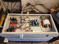
Attachments
Last edited:
Have you worked on the pots P1+P2? They set the bias voltage for the output mosfets. If one output mosfet is biased higher, you get dc offset. As it is only 8 V the mosfets are probably okay. If nothing happens when you turn P1+P2, you could measure the gate voltage on the output mosfets (R8+R9), voltage drop across R6/R7?
Attachments
Have you worked on the pots P1+P2? They set the bias voltage for the output mosfets. If one output mosfet is biased higher, you get dc offset. As it is only 8 V the mosfets are probably okay. If nothing happens when you turn P1+P2, you could measure the gate voltage on the output mosfets (R8+R9), voltage drop across R6/R7?
Thanks ozorfis,
I have only two DMMs on hand at present. Need to borrow another to adjust the bias.
you have output cap and bleeder resistor after?
asking , confused with "at RCA" part
By RCA, i meant signal out.
Offset is measured before the capacitor… The capacitor should block all DC at the output RCA, reading DC there is odd.
Yes, you need 3 meters to set bias/offset.
Yes, you need 3 meters to set bias/offset.
yeah, you're acccccccustomed to have full table in front of you, while flying 🙂
for me - even 3 DMMs are not enough, but we all know that I'm Weakling
for clever Greedy Boy - 2 are enough - one observing output node voltage, second observing one source resistor (of one output mosfet)

for me - even 3 DMMs are not enough, but we all know that I'm Weakling
for clever Greedy Boy - 2 are enough - one observing output node voltage, second observing one source resistor (of one output mosfet)
I managed with 2, verifying the other MOSFET afterwards. Since I am so insanely clever 
No, because my neighbour reclaimed his Fluke. And two worked.
But still, something sounds way off, and 6L6 is as usual right on the mark. Pic would help.
No, because my neighbour reclaimed his Fluke. And two worked.
But still, something sounds way off, and 6L6 is as usual right on the mark. Pic would help.
simple as this:
observing current of one mosfet and setting the same, while setting second mosfet and observing & chasing proper DC level of output node, inevitably ends in both mosfets having same Iq
though, as I said , even 3 DMMs are usually not enough for Chicken ZM
observing current of one mosfet and setting the same, while setting second mosfet and observing & chasing proper DC level of output node, inevitably ends in both mosfets having same Iq
though, as I said , even 3 DMMs are usually not enough for Chicken ZM
How is channel balanced affected by the circuit/adjusted? I’m seeing a 3% skew to the right, enough to notice. I’ve already verified the source signal is correct. Is there anything I can do to center it?
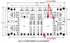
Please confirm resistor values of R8, R9, R10, R11 and R13, both channels.
Edit: these set the voltage gain. Adjusting IQ, offset and P3 does not affect gain.
Regards,
Andy
Edit: these set the voltage gain. Adjusting IQ, offset and P3 does not affect gain.
Regards,
Andy
Last edited:
How is channel balanced affected by the circuit/adjusted? I’m seeing a 3% skew to the right, enough to notice. I’ve already verified the source signal is correct. Is there anything I can do to center it?
In addition:
If I remember correctly, more bias means a little more gain - so check, if your bias current is the same on each channel - I could be wrong though

I think Ozorfis is right, though I haven’t experienced differences myself wrt gain vs bias. Either way, the starting point of troubleshooting is with equal IQ both sides, and zeroed offset.
I played with output bias a bit, but it didn’t have an effect. I’m going to balance all the resistors you mentioned.
To clarify, is DC offset measured across R12 or R13? The guide says R12, but I’ve never seen that value swing, whereas R13 does swing and can be balanced by R10 and R11.
To clarify, is DC offset measured across R12 or R13? The guide says R12, but I’ve never seen that value swing, whereas R13 does swing and can be balanced by R10 and R11.
to SoaDMTGguy #976
Hello SoaDMTGguy,
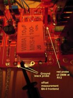
do you want to measure the DC-offset of your BA-3 frontend -
this is measured in front of the outputcap (between R12 and C3) referenced to ground. Is adjusted with P1 and P2 on the frontendboard.
Or do you want to measure your DC-offset at speakeroutput?
P1 and P2 (Pot 101 and 102 in the schematic) on the bias-boards of the outputstage do this.
Cheers
Dirk 😀
Hello SoaDMTGguy,
do you want to measure the DC-offset of your BA-3 frontend -
this is measured in front of the outputcap (between R12 and C3) referenced to ground. Is adjusted with P1 and P2 on the frontendboard.
Or do you want to measure your DC-offset at speakeroutput?
P1 and P2 (Pot 101 and 102 in the schematic) on the bias-boards of the outputstage do this.
Cheers
Dirk 😀
to SoaDMTGguy
This is where you measure the DC-offset of the BA-3 fronentboard.
Also keep an eye on your bias over R10 and R11. Shouldn:t be much higher than 1V. If you have enough heatsink perhaps higher.
Greets
Dirk
This is where you measure the DC-offset of the BA-3 fronentboard.
Also keep an eye on your bias over R10 and R11. Shouldn:t be much higher than 1V. If you have enough heatsink perhaps higher.
Greets
Dirk
Attachments
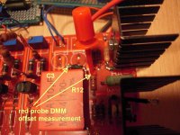
Ok, so +probe should start at the top of P3 *or* R12, and the negative should be on ground.
Is there a reason to do this instead of messing *across* R12? Is that equivalent, or different?
Is there a reason to do this instead of messing *across* R12? Is that equivalent, or different?
- Home
- Amplifiers
- Pass Labs
- BA-3 Amplifier illustrated build guide