WHA-217 E2 on NHB-108 base
PRESENTATION
This is (and will be [never say never again]) my last elaboration on NHB-108 base. It is a dual-mono building. About the name: "WOTS" stays for "Warmth Of The Sound", "WHA" stays for "Will Hear Again" meaning you'll hear music every time you turn it on, while "NHB - Never Heard Before" doesn't sound that auspicious, "217" is double of "108" plus 1, "E2" could be "Enhanced version 2" or some other fancy meaning you can imagine; actually it is transposed from Roman slang, meaning "another one, the second"
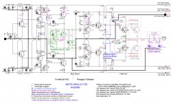
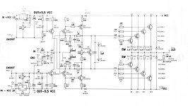
The power of this amplifier is 200Wrms/8Ohms per channel with the capability to drive very low impedance loads. This performance is achieved by adding a follower to the original Diamond Buffer final stage, being this add-on made by 15 paralleled couples. This final stage takes the name of "Paragon Follower". All stages work in "Class A" but the final pairs, working in "Class B"
The peculiar characteristic of this amplifier is to have no feedback from the speaker output, like the original base NHB-108.
PHILOSOPHY OF THE (MODIFICATION TO THE) PROJECT
Music is emotion. If you listen to music and do not feel any emotion, something is wrong. Where is the emotion? It is trapped in the feedback loop!
All 3 last HiEnd amplifiers I built have no loop feedback. I will never step back building again any other amplifier with the feedback loop starting from the speaker end, unless I need it for a purpose other than the High End High Fidelity one. And, in that case, I would prefer the LJM L20 V9.2. But this is another story.
This project is the easiest way to build a Hi-End component with no feedback from the speaker end, because it is the only PCB I could find on the market with this feature. There are better projects sporting this feature for sure, but you have to design and make the PCB by yourself. Being no feedback from the speaker end, in order to achieve a good damping factor you have to use a lot of final pairs, at least six. The internal loop feedback, an evil that we cannot do less in a solid-state amplifier, is well insulated from the speaker reactions by the final stage "Paragon follower".
HISTORY
I have been working on this project for over a year, I posted it here some time ago. My last post was #2057. I don't remember the exact history, some of you proposed a Baxandall super couple (see T5/T8 and T6/T10 in my schematic), and some other attempts at improvement. I implemented them all on my WHA-217 Cu Edition because, from the tech side, they were valid. But I didn't like the result compared to the precedent build (circuitry on main PCB almost untouched), so I didn't replicate those mods on this "E2" version, and when it is ready to operate, I will remove all those mods to the Cu Edition.
CIRCUITRY
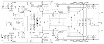
TOPOLOGY GAIN STAGE - The topology of the gain stage is almost untouched, compared to the NHB-108: the midpoint trimmer and associated components were removed (a lot of hum from that circuit), the feedback loop is slightly changed in order to have a single input point for the feedback, instead of two. This also avoids altering, even minimally, the polarization of T3, T4, which would happen (in the original circuitry) in consequence of having inserted a xVbe. Some transistors are replaced avoiding the MJE15032/MJE15033 pair, because of their huge difference in NPN/PNP hFE. T5/T6 pair are Toshiba TTC004B/TTA004B, and T8/T10 pair are Sanken 2SA1859A/2SC4883A. I also removed the input capacitor because I know how my preamplifiers are equipped (capacitor and short circuit at output with 3 minutes delay), so the input capacitor, for me, would have been one more useless capacitor in the signal path.
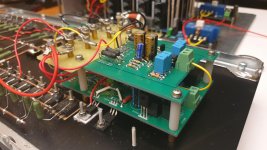
XVBE - A xVbe was implemented, for the bias setting and the temperature tracking. It is made out of a Sziklai couple, to allow a low impedance, a low sensitivity to the voltage variations, a good tracking capability, highly needed, because very low 0.1Ohm emitter resistors are used in the final pairs, and we don't want a thermal avalanche. The xVbe board is to be housed among the final pairs, in order to sense their heat. Another help controlling the temperature is from the pre-driver stage, whose transistors are to be put close to the final pairs.
FINAL STAGE - The final stage is confirmed to be the "Paragon Follower" of the Cu Edition, without NSCB circuit (leading to auto-oscillation), with upgraded CCS's, now delivering only 12.5mA. According to D.Self, since all final transistors have a very close hFE, 0.1Ohm resistors were chosen as Re's, in order to minimize the bias and the distortion. No other changes with respect to the last WHA-217 but the transistors used. The pair TTA1943/TTC5200, surely oversized, has been chosen as a driver because of its low Cob and high current feature, but it is not critical to exactly use this couple. Obviously, the diodes driving the base of the former final pair are no more needed. Let's spend some words about these diodes: their function is very simple, the two 27Ohm resistors put on the bases of the final pair establish the bias (the lower the resistance, the higher the bias) and bring the driving signal to the final pair. When the driving signal becomes stronger, the two resistors wouldn't allow the final pairs to be driven at full power so the two diodes switch on, allowing the full driving of the final pairs. IMHO this solution limits the choice of speakers you can use with this amp. For instance, it absolutely refuses to drive my Acoustat 1+1.
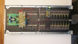
POWER SUPPLY UNIT: it is the classical simple one with 10x 6.8mF/100V capacitors/rail/channel = 40x 6.8mF/100V for the high current section "Paragon Follower", and 1x 4.7mF/100V capacitor/rail/channel = 4x 4.7mF/100V for the low current gain stage section VAS. I implemented a simple solution that allows the voltage on the VAS to be almost constant, by decoupling its power lines by a diode couple. I bought the bare PCBs on eBay, 6 boards (for stereo) holding 8 x 35mm capacitors each.
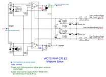
SERVO: Since the internal feedback loop is partialized even in DC (no decoupling capacitor is present), and since the feedback is the current type, in order to maintain the midpoint at zero, a servo circuit is highly advisable. The one sold in eBay (both old and new 2020.05 editions) has two main issues. First about components: extremely cheap film capacitors are used, while they must be high quality and (very important) low tolerance ones, and the OpAmp must be a precision one. Second: even with the best OpAmp, it will be impossible to have exactly the same offset tracking on both outputs. But, in our case, this is not a real issue because only one section of the servo will be used lowering its Routput to 16600Ohm, not really critical, a 15-:-18KOhm resistor will be ok. Otherwise one can decide to use both sections with outputs paralleled. I did. Other improvements are possible (2020.05 edition): the two electrolytic capacitors were substituted with two 1mF 25V ones, and the ones removed were put in parallel with the 12KOhm resistors, according to the best practice for the TL413A shunt regulator. A 10MOhm resistor, paralleled with the capacitor in the feedback loop, could help the function of the servo; I didn't try it yet, but, in this case, the output resistor must be lowered from to about 4-:-10KOhm. There will be no way that this upgraded servo can spoil the sound quality.
SPEAKER PROTECTION: I bought two stereo boards from eBay, each made of two big and good 30A relays that I paralleled. Rectification and delay capacitors were substituted with 1mF 25V/220uF 6.3V ones in order to achieve a higher Vdc and a longer 20 seconds delay time; moreover, the other 220uF capacitors among the two relays were substituted by another with the same value but long leads, assembled upside down, in order to connect a fan socket to its leads; then the fan socket was glued among the two relays. Since each board will be used for one channel, the contacts of the relays must be paralleled.
FANS: they are not strictly mandatory but it would be better to move the air inside the cabinet, where all things are going to generate some heat. The fans will rotate at a low speed without making any noise. I used two Noctua NF-B9 Redux 3 pin; a 50 -:- 150Ohm resistor is needed for each fan, in order to reduce its speed and keep it silent.
SOFT START: I bought a board on eBay with a 100A (!) relay. This board has an original delay time too fast to work correctly with 0.3F total capacity. Also it uses 4 NTCs that are not suitable to handle correctly the power needed when a longer delay time is configured. But this board is the best you can find at an affordable price. So, some modifications are needed: remove all NTCs and use a halogen bulb as a damper load; change the timing capacitor with a 220uF 25V that will configure about 8 seconds of delay, reinforce the high current tracks by melting some tin on them.
PLACING FINAL PAIRS - In my layout it is better to put the transistors with higher hFE on the first heatsink, the one holding the mainboard.
FIRING UP - Mandatory: use a bench power supply with low-value capacitors and a variac. Put together the "VAS" and "Paragon Follower" power rails. Do not be worried about the hum you will hear, it will disappear once you connect the real power supply. The hum is very welcome in this phase, it allows you to understand the amp is alive and if it is drawing too much current (by the tune of the hum). Insert a 1Ohm resistor in one collector's rail of the final pairs (any, + or - makes no difference) and connect the millivoltmeter across this resistor. Connect the heatsink to the mass (do not leave it floating) with a double alligator cable, and fire up now rising the variac to 10Vcc. Read the millivoltmeter; lower the reading to its minimum possible using the bias trimmer. When done, start rising the voltage by the variac: the current drawing will decrease a lot. If no explosion nor smoke is detected, reach gradually the 140Vcc, read the millivoltmeter and adjust the bias until it shows 65mV which, on 1Ohm, are 65mA.
When you are ready to use both channels, it is preferable to connect together the two mass connections of the input pin jacks RCA.
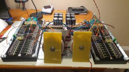
AT PRESENT: Today I closed the amplifier, it has been playing for 15 hours, it is really powerful in driving the speaker. @65mA idle it is completely cold while listening at low volume. The sound seems to be very precise. I cannot say more, I have to listen to it for a longer time, even if at the first impression it seems extremely good. After 15 hours of continuous listening, I can state without any doubt that no listening fatigue has occurred at all, the music was really pleasant.
Mechanical notes.
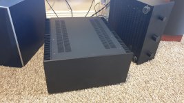
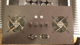
I chose the HiFi2000's Dissipante 5U/500mm with its internal base. The front panel remained untouched, the rear panel holds the two fans, the input pin jacks, the speaker's binding posts, the IEC C20 socket, and a fuse holder. The internal base was adapted with some drilling, to hold the "castle" of capacitors and all the rest.
The biggest work was the drilling on the heat sinks in order to hold the mainboards and the final pairs: 104 threaded holes in total. You need to use good taps. With mine mounted on the tap wrench, I was able to thread with two fingers, applying a very low torque while using a tap able to expel chips from the other end of the hole. All holes are through-hole but 4, in order to thread these 4 holes a different tap and a stronger torque are needed, together with some ability. To make the tap as vertical as possible use the drill-press as a guide (see pictures). While treading use the turpentine as a lubricant. Once all threading work has finished, use a brake cleaner spray to clean away the turpentine, allowing the use of a thread lock. Once you put in place all studs with the thread lock fluid, tension them by using a nut and a spacer (see pictures); do not put in place the nut without a spacer because the thread lock will lock the nut on the stud.
My friend Paolo, building the thing at the same time, resolved the hosting of the two transformers close to the front panel. I made them removable so, when I have to move the amplifier I don't have to lift 100 lbs or more at once. He convinced me to thread the holes of the final pairs and taught me how to do, what I would have never suspected to be that easy and precise!
The leads of the final pairs must be bent in the way described in the picture. In order to bend them correctly, I used a prying tool 4mm thick.
Should some be interested, I have all the BOM and pictures taken during assembling my WHA-217 E2, just let me know in a PM.
PRESENTATION
This is (and will be [never say never again]) my last elaboration on NHB-108 base. It is a dual-mono building. About the name: "WOTS" stays for "Warmth Of The Sound", "WHA" stays for "Will Hear Again" meaning you'll hear music every time you turn it on, while "NHB - Never Heard Before" doesn't sound that auspicious, "217" is double of "108" plus 1, "E2" could be "Enhanced version 2" or some other fancy meaning you can imagine; actually it is transposed from Roman slang, meaning "another one, the second"
The power of this amplifier is 200Wrms/8Ohms per channel with the capability to drive very low impedance loads. This performance is achieved by adding a follower to the original Diamond Buffer final stage, being this add-on made by 15 paralleled couples. This final stage takes the name of "Paragon Follower". All stages work in "Class A" but the final pairs, working in "Class B"
The peculiar characteristic of this amplifier is to have no feedback from the speaker output, like the original base NHB-108.
PHILOSOPHY OF THE (MODIFICATION TO THE) PROJECT
Music is emotion. If you listen to music and do not feel any emotion, something is wrong. Where is the emotion? It is trapped in the feedback loop!
All 3 last HiEnd amplifiers I built have no loop feedback. I will never step back building again any other amplifier with the feedback loop starting from the speaker end, unless I need it for a purpose other than the High End High Fidelity one. And, in that case, I would prefer the LJM L20 V9.2. But this is another story.
This project is the easiest way to build a Hi-End component with no feedback from the speaker end, because it is the only PCB I could find on the market with this feature. There are better projects sporting this feature for sure, but you have to design and make the PCB by yourself. Being no feedback from the speaker end, in order to achieve a good damping factor you have to use a lot of final pairs, at least six. The internal loop feedback, an evil that we cannot do less in a solid-state amplifier, is well insulated from the speaker reactions by the final stage "Paragon follower".
HISTORY
I have been working on this project for over a year, I posted it here some time ago. My last post was #2057. I don't remember the exact history, some of you proposed a Baxandall super couple (see T5/T8 and T6/T10 in my schematic), and some other attempts at improvement. I implemented them all on my WHA-217 Cu Edition because, from the tech side, they were valid. But I didn't like the result compared to the precedent build (circuitry on main PCB almost untouched), so I didn't replicate those mods on this "E2" version, and when it is ready to operate, I will remove all those mods to the Cu Edition.
CIRCUITRY
TOPOLOGY GAIN STAGE - The topology of the gain stage is almost untouched, compared to the NHB-108: the midpoint trimmer and associated components were removed (a lot of hum from that circuit), the feedback loop is slightly changed in order to have a single input point for the feedback, instead of two. This also avoids altering, even minimally, the polarization of T3, T4, which would happen (in the original circuitry) in consequence of having inserted a xVbe. Some transistors are replaced avoiding the MJE15032/MJE15033 pair, because of their huge difference in NPN/PNP hFE. T5/T6 pair are Toshiba TTC004B/TTA004B, and T8/T10 pair are Sanken 2SA1859A/2SC4883A. I also removed the input capacitor because I know how my preamplifiers are equipped (capacitor and short circuit at output with 3 minutes delay), so the input capacitor, for me, would have been one more useless capacitor in the signal path.
XVBE - A xVbe was implemented, for the bias setting and the temperature tracking. It is made out of a Sziklai couple, to allow a low impedance, a low sensitivity to the voltage variations, a good tracking capability, highly needed, because very low 0.1Ohm emitter resistors are used in the final pairs, and we don't want a thermal avalanche. The xVbe board is to be housed among the final pairs, in order to sense their heat. Another help controlling the temperature is from the pre-driver stage, whose transistors are to be put close to the final pairs.
FINAL STAGE - The final stage is confirmed to be the "Paragon Follower" of the Cu Edition, without NSCB circuit (leading to auto-oscillation), with upgraded CCS's, now delivering only 12.5mA. According to D.Self, since all final transistors have a very close hFE, 0.1Ohm resistors were chosen as Re's, in order to minimize the bias and the distortion. No other changes with respect to the last WHA-217 but the transistors used. The pair TTA1943/TTC5200, surely oversized, has been chosen as a driver because of its low Cob and high current feature, but it is not critical to exactly use this couple. Obviously, the diodes driving the base of the former final pair are no more needed. Let's spend some words about these diodes: their function is very simple, the two 27Ohm resistors put on the bases of the final pair establish the bias (the lower the resistance, the higher the bias) and bring the driving signal to the final pair. When the driving signal becomes stronger, the two resistors wouldn't allow the final pairs to be driven at full power so the two diodes switch on, allowing the full driving of the final pairs. IMHO this solution limits the choice of speakers you can use with this amp. For instance, it absolutely refuses to drive my Acoustat 1+1.
POWER SUPPLY UNIT: it is the classical simple one with 10x 6.8mF/100V capacitors/rail/channel = 40x 6.8mF/100V for the high current section "Paragon Follower", and 1x 4.7mF/100V capacitor/rail/channel = 4x 4.7mF/100V for the low current gain stage section VAS. I implemented a simple solution that allows the voltage on the VAS to be almost constant, by decoupling its power lines by a diode couple. I bought the bare PCBs on eBay, 6 boards (for stereo) holding 8 x 35mm capacitors each.
SERVO: Since the internal feedback loop is partialized even in DC (no decoupling capacitor is present), and since the feedback is the current type, in order to maintain the midpoint at zero, a servo circuit is highly advisable. The one sold in eBay (both old and new 2020.05 editions) has two main issues. First about components: extremely cheap film capacitors are used, while they must be high quality and (very important) low tolerance ones, and the OpAmp must be a precision one. Second: even with the best OpAmp, it will be impossible to have exactly the same offset tracking on both outputs. But, in our case, this is not a real issue because only one section of the servo will be used lowering its Routput to 16600Ohm, not really critical, a 15-:-18KOhm resistor will be ok. Otherwise one can decide to use both sections with outputs paralleled. I did. Other improvements are possible (2020.05 edition): the two electrolytic capacitors were substituted with two 1mF 25V ones, and the ones removed were put in parallel with the 12KOhm resistors, according to the best practice for the TL413A shunt regulator. A 10MOhm resistor, paralleled with the capacitor in the feedback loop, could help the function of the servo; I didn't try it yet, but, in this case, the output resistor must be lowered from to about 4-:-10KOhm. There will be no way that this upgraded servo can spoil the sound quality.
SPEAKER PROTECTION: I bought two stereo boards from eBay, each made of two big and good 30A relays that I paralleled. Rectification and delay capacitors were substituted with 1mF 25V/220uF 6.3V ones in order to achieve a higher Vdc and a longer 20 seconds delay time; moreover, the other 220uF capacitors among the two relays were substituted by another with the same value but long leads, assembled upside down, in order to connect a fan socket to its leads; then the fan socket was glued among the two relays. Since each board will be used for one channel, the contacts of the relays must be paralleled.
FANS: they are not strictly mandatory but it would be better to move the air inside the cabinet, where all things are going to generate some heat. The fans will rotate at a low speed without making any noise. I used two Noctua NF-B9 Redux 3 pin; a 50 -:- 150Ohm resistor is needed for each fan, in order to reduce its speed and keep it silent.
SOFT START: I bought a board on eBay with a 100A (!) relay. This board has an original delay time too fast to work correctly with 0.3F total capacity. Also it uses 4 NTCs that are not suitable to handle correctly the power needed when a longer delay time is configured. But this board is the best you can find at an affordable price. So, some modifications are needed: remove all NTCs and use a halogen bulb as a damper load; change the timing capacitor with a 220uF 25V that will configure about 8 seconds of delay, reinforce the high current tracks by melting some tin on them.
PLACING FINAL PAIRS - In my layout it is better to put the transistors with higher hFE on the first heatsink, the one holding the mainboard.
FIRING UP - Mandatory: use a bench power supply with low-value capacitors and a variac. Put together the "VAS" and "Paragon Follower" power rails. Do not be worried about the hum you will hear, it will disappear once you connect the real power supply. The hum is very welcome in this phase, it allows you to understand the amp is alive and if it is drawing too much current (by the tune of the hum). Insert a 1Ohm resistor in one collector's rail of the final pairs (any, + or - makes no difference) and connect the millivoltmeter across this resistor. Connect the heatsink to the mass (do not leave it floating) with a double alligator cable, and fire up now rising the variac to 10Vcc. Read the millivoltmeter; lower the reading to its minimum possible using the bias trimmer. When done, start rising the voltage by the variac: the current drawing will decrease a lot. If no explosion nor smoke is detected, reach gradually the 140Vcc, read the millivoltmeter and adjust the bias until it shows 65mV which, on 1Ohm, are 65mA.
When you are ready to use both channels, it is preferable to connect together the two mass connections of the input pin jacks RCA.
AT PRESENT: Today I closed the amplifier, it has been playing for 15 hours, it is really powerful in driving the speaker. @65mA idle it is completely cold while listening at low volume. The sound seems to be very precise. I cannot say more, I have to listen to it for a longer time, even if at the first impression it seems extremely good. After 15 hours of continuous listening, I can state without any doubt that no listening fatigue has occurred at all, the music was really pleasant.
Mechanical notes.
I chose the HiFi2000's Dissipante 5U/500mm with its internal base. The front panel remained untouched, the rear panel holds the two fans, the input pin jacks, the speaker's binding posts, the IEC C20 socket, and a fuse holder. The internal base was adapted with some drilling, to hold the "castle" of capacitors and all the rest.
The biggest work was the drilling on the heat sinks in order to hold the mainboards and the final pairs: 104 threaded holes in total. You need to use good taps. With mine mounted on the tap wrench, I was able to thread with two fingers, applying a very low torque while using a tap able to expel chips from the other end of the hole. All holes are through-hole but 4, in order to thread these 4 holes a different tap and a stronger torque are needed, together with some ability. To make the tap as vertical as possible use the drill-press as a guide (see pictures). While treading use the turpentine as a lubricant. Once all threading work has finished, use a brake cleaner spray to clean away the turpentine, allowing the use of a thread lock. Once you put in place all studs with the thread lock fluid, tension them by using a nut and a spacer (see pictures); do not put in place the nut without a spacer because the thread lock will lock the nut on the stud.
My friend Paolo, building the thing at the same time, resolved the hosting of the two transformers close to the front panel. I made them removable so, when I have to move the amplifier I don't have to lift 100 lbs or more at once. He convinced me to thread the holes of the final pairs and taught me how to do, what I would have never suspected to be that easy and precise!
The leads of the final pairs must be bent in the way described in the picture. In order to bend them correctly, I used a prying tool 4mm thick.
Should some be interested, I have all the BOM and pictures taken during assembling my WHA-217 E2, just let me know in a PM.
Attachments
-
 Electronics 01 Schematic 01 Amplifier.JPG813.6 KB · Views: 1,754
 -
 Electronics 01 Schematic 02 Servo.JPG231.4 KB · Views: 1,846
 -
 Electronics 01 Schematic 03 Power Supply.JPG122.5 KB · Views: 1,344
 -
 Assembly 80 The whole thing 01.jpg988.2 KB · Views: 1,224
 -
 Assembly 80 The whole thing 03.jpg992.4 KB · Views: 1,144
 -
 Assembly 90 The WHA-217 E2 02.jpg979.9 KB · Views: 879
 -
 Assembly 09 Rear Panel.jpg748.4 KB · Views: 819
 -
 Assembly 10 Right channel 01.jpg839.1 KB · Views: 956
 -
 Assembly 10 Right channel 02.jpg810 KB · Views: 1,395

Thank you Analog_Sa, I really appreciate your interest and I'm glad you like the project.
The original 108 shows a good VAS but needed a pair of wings, here they are. I cannot say this is a simple project but I can affirm this is a fully satisfying one once you hear its sound.
My last post contains some mistakes, where you see Vcc, read Vdc and some pictures referenced in the text are not present, actually, those pictures are needed only if you want to build the thing. Moreover, on the Servo Schematic:
- R105 should be blue;
- first green note: "R103" is to be read "R107";
- second green note: "If used only OpAmp upper section R103=15Kr, do not connect R104 to R104" is to be read "If used only OpAmp upper section R107=15Kr, do not connect R107 to R108.".
A strange aspect of this build is the incredible number of fasteners and ring connectors I had to use. Counting them all was impossible for me.
Last edited:
Is dartzeel NHB 458 / 468 a balanced amplifier ?
Attachments
-
 NHB-468 .jpg311.7 KB · Views: 2,101
 -
 M-5.jpg381.9 KB · Views: 1,352
 -
 darTZeel NHB-468.jpg236.5 KB · Views: 933
 -
 darTZeel NHB 468.jpg925.9 KB · Views: 880
 -
 darTZeel NHB-458.jpg666.8 KB · Views: 979
 -
 DarTZeel---NHB 458.jpg65.9 KB · Views: 1,156
 -
 darTZeel NHB 458.jpg701.9 KB · Views: 1,152
 -
 darTZeel NHB 458 3D.jpg203.4 KB · Views: 1,125
No, they aren't.
Many thanks for posting the 468's schematic. Some must have copied from someone else!
Many thanks for posting the 468's schematic. Some must have copied from someone else!
So you don't like feedback, so you only use feedback around the VAS? Doesn't make any sense at all to me - the OS is where the feedback is most needed to knock back the crossover artifacts.
I don't like feedback at all. With Mr. Deletraz we are at least two of us.
All my preamplifiers (Tubes, Hybrid, Solid State) have only local feedback; loop feedback is out of the discussion. My tube main amplifiers are designed in the same way. All DIYers and passionate people who use to visit me seem to appreciate their sound.
In a SS main amplifier with two gain stages VAS, the use of the feedback is mandatory. If you close the loop inside the VAS itself and have a triple devices output stage out of the feedback loop, there is no way that the reaction of the speaker could be injected in significant quantity in the signal path. So the VAS and its feedback work in a linear environment, with no reactive components (unless the compensation capacities). If you draw the feedback signal from the speaker output, you get and inject the reaction of the speaker in the signal path, that is not the signal.
If the OS is well designed (multiple devices, correct bias), its artifacts will be a lot less bad than the ones generated by the attempt to correction of the feedback.
It doesn't make any sense at all to me to introduce an error and correct it afterward. I prefer caring to avoid or minimize the error as much as possible.
Does it make sense to you?
A deliberate asymmetric push-pull operation ( by the asymmetric complementer transistor pairs ) can be a part of darTZeel basis theory. Creating higher level even-numbered harmonics than high level other existing harmonics to achieve a planned sound...and to present a wonderful parameter to the audiophiles...PRESENTATION
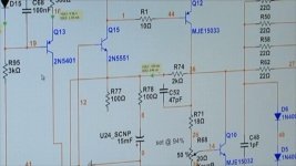
.... Some transistors are replaced avoiding the MJE15032/MJE15033 pair, because of their huge difference in NPN/PNP hFE. ..
Sometimes worse is better 🙂
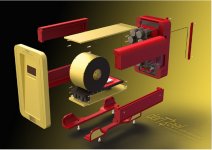
Pictures:Is dartzeel NHB 458 / 468 a balanced amplifier ?
1. ...
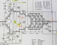
2. it can be similar to NHB 458's schematic
3. a part of the schematic of NHB 458
4. chinese NHB 108 version
5. chinese NHB 108 version
6. ...
7. diamond buffer structure
8. my own amp's schematic ( not dartzeel )
The schematic of NHB 468 is unknown. I suppose, it similar to NHB 458.
Both of these amps have asymmetric structures, and they have balanced to unbalanced converters by OPAs.
A deliberate asymmetric push-pull operation ( by the asymmetric complementer transistor pairs ) can be a part of darTZeel basis theory. Creating higher level even-numbered harmonics than high level other existing harmonics to achieve a planned sound...and to present a wonderful parameter to the audiophiles...
Sometimes worse is better 🙂
I am a mere mortal enthusiast, not an amplifier factory, so I have to settle for what I find on the market, buying with a small surplus, in order to make a minimum of selection. We are however talking about a complementary pair, so the correspondence in some way/time/place must exist. A factory like Dartzeeel, given the high prices it asks, can request matched transistor pairs from manufacturers. I can't believe the big NPN/PNP difference is a deliberate fact. I believe that the original is made with highly selected components.
good sir i just want to ask you if this amp circuit giagram working sir with out changing parts sir? thanks@Hattori, drmaftoon
First of all, I have to say that the spreadsheet I uploaded in my last post, is a simplified one, it does not take into account the idle current and some other technicalities. I made a more precise spreadsheet but the result of the two are very similar and the trend is exactly the same.
Second of all, I must say that you need some skill to operate the upgrade to WHA-217, if you do, the mod will be very simple. You need also a variac.
As a first step, you have to remove all the final pairs and their emitter resistors from your board, the final pair you removed could be the new final pairs if you plan to use 3 pairs, which is the minimum number.
On the PCB you must replace one former final pair with another "pilot" pair, which can be the same MJL transistors or something else with 40W and 180Vce at least, and hFE > 80 and a SOA compatible with the job. You cannot get wrong by following my schematic and search the market for pairs with features similar to mine or better.
Mount new emitter resistors 4.7KOhm 5W at least (I used 10W WW ones), connected to the opposite pole of the power line. This should be easy to do on the board itself, the empty collector holes of the removed pairs can be used for the two new resistors.
Then you have to desolder the first and the last TO220 transistor to operate the modification required by the schematic and change the resistors of the CCSs to the new values.
Remove the trimmer and the two resistors with it. Solder the 100KOhm resistor as per schematic.
Remove the 2N5xx1 pairs and replace them with other pairs thermically connected (thermal glue and 0.3mm copper foil you can find on eBay).
As per 3SSS modification, you should use a 2N5551/2N5401 pair in place of the first TO220 pair, I understood this too late. I wouldn't change the two emitter resistors (with one of doubled value) of this pair as I did because it worsens the rejections to power disturbances.
Then you have to think about the arrangement of the remaining components of the NSCB stage; on my PCB it was impossible to make room for the new components and I used another small board, as you saw in my post.
On your PCB you have to cut the track bringing the speaker sensing to the servo, which will be connected to the new speaker point of the added NSCB stage.
You have to find room on the heatsink for the new final pairs you will adopt, plus the pair of temperature sensing transistors, which I connected to the mainboard with a couple of Noctua 3 wires computer fan extensions.
The temperature sensing transistors have only one requirement, the hFE must be > 100, while Vce/Ic are not critical, provided they are > 50V/1A, the case can be any type having the metallic plate that interfaces the heatsink.
As a final pair, you can use the pairs you removed or any good pairs with a matched hFE > 80 and Vce > 180V, whose SOA is compatible with the job; the MT200 final pairs I have are not sold anymore, I recommend not less than 3 pairs, avoiding to buy fakes on eBay.
The output coils are made with 10 turns of AWG14 enameled wire on a 1" plastic pipe, the capacitors close to the coil must be 1000Vdc because they are crossed by a non-negligible current and the 1000V ones are big enough.
The 42Vac transformer will be good, you will get 58+58Vdc voltage, and a little less than 150WRMS, limited in current only by the final pairs and the power supply capabilities, theoretically limited by the CCSs current multiplied by hFE(diamond) X hFE(NSCB). Only theoretically.
What is not good at all are the capacitors on the power supply boards, mine swell all at 70+70V.
Follow the schematic on this post, where I put in place again the original emitter resistors of the first TO220 pair.
As a cabinet, if you don't have any, I would choose a "Dissipante" by HiFi2000 - modushop.biz
If you have any question you can send me a PM, I will answer asap, hoping the power in US will never leave us in blackout!
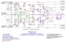
The post you are referring to is an old post of mine, I modified that schematic, the new one is at post #2081.
It works without depending on the speakers you connect to it.
The NHB-108 original circuit works.
How does it work? It depends on your speakers.
What is your aim?
It works without depending on the speakers you connect to it.
The NHB-108 original circuit works.
How does it work? It depends on your speakers.
What is your aim?
Hello marigno
greetings #2081 schematic can it work with 4 output pairs in 4ohm/8ohm
speakers at 55 dc +/- supply rails.
warm regards
Andrew
greetings #2081 schematic can it work with 4 output pairs in 4ohm/8ohm
speakers at 55 dc +/- supply rails.
warm regards
Andrew
Hello Andrew,
keep in mind we have no feedback from the speaker, so the more the pairs, the better. The driver stage is strong enough to drive a long string of final pairs. I would say 6 pairs should be the minimum but there is no reason to prevent 4 pairs to work well enough.
I think you will not find exactly the pairs I used (very good multi-emitter transistors), they are now deprecated. I chose the "Y" hFE selection and they were bought by my friend Paolo from some distributor. Mouser and DigiKey don't have them or have different NPN/PNP selections so you don't want to buy them. Actually, any good final pair will work, even the one I used as a driver (TTA1943/TTC5200) will be also a good final pair, their hFE is not that different.
To be sincere, all transistors in my scheme are now deprecated but the Toshiba ones (TTAxxxx/TTCxxxx), so you have to figure out what to use for TO220 devices. Mouser and Digikey have a very good search engine. For instance, a possible choice for TO220 devices can be 2SC4381/4382 and 2SA1667/1668; since you want to use a 110Vdc supply, all of them will fit.
I advise you to not use the MJE1503x pair, first of all, they are not that suitable, then the difference of hFE among NPN/PNP is too big. Do not buy the TO126 and TO220 transistors from eBay, I got a bunch of fakes, while the 2N5x01 bought on eBay were very good ones (it is not worth manufacturing fakes for them).
The schematic you see here has some corrections with respect to the last one, so follow this one.
If you want really to go further and build this amplifier, you need the whole set of documents, send me a PM and I will send them via WeTransfer to your email address.
Attachments
thanks for your input! in your decisions you have killed many pain points of the original scheme 🙂. It's a great idea with an integrator to inject it at the diamond buffer output rather than the input. It is highly undesirable to tamper with the input in the diamond buffer, especially with "dirt" from the power rails. Well, all the other solutions are very useful. It is not entirely clear why you abandoned the use of a pair of Baksandal ... In my case it had a positive effect, I just had to change the correction a little.PRESENTATION
This is (and will be [never say never again]) my last elaboration on NHB-108 base. It is a dual-mono building. About the name: "WOTS" stays for "Warmth Of The Sound", "WHA" stays for "Will Hear Again" meaning you'll hear music every time you turn it on, while "NHB - Never Heard Before" doesn't sound that auspicious, "217" is double of "108" plus 1, "E2" could be "Enhanced version 2" or some other fancy meaning you can imagine; actually it is transposed from Roman slang, meaning "another one, the second"
The power of this amplifier is 200Wrms/8Ohms per channel with the capability to drive very low impedance loads. This performance is achieved by adding a follower to the original Diamond Buffer final stage, being this add-on made by 15 paralleled couples. This final stage takes the name of "Paragon Follower". All stages work in "Class A" but the final pairs, working in "Class B"
The peculiar characteristic of this amplifier is to have no feedback from the speaker output, like the original base NHB-108.
Now I remember! You suggested about Baxandall mod.
The last edition of my build has a sound I don't like that much. I suspect about Baxandall Pair and too low bias. But I'm pretty sure I didn't touch the bias setting after operating the Baxandall mod. Will see. I have to tear it down and verify. Now I have the "E2" edition and can operate on the old one. As soon I get some hardware I need, I'll start, and keep you posted.
The last edition of my build has a sound I don't like that much. I suspect about Baxandall Pair and too low bias. But I'm pretty sure I didn't touch the bias setting after operating the Baxandall mod. Will see. I have to tear it down and verify. Now I have the "E2" edition and can operate on the old one. As soon I get some hardware I need, I'll start, and keep you posted.
You're right, the overall sound is changing. But I think the amplifier as a whole is becoming more accurate and faster, but if you take into account the combination with other components of the system, the effect can be both positive and negative.I am a mere mortal enthusiast, not an amplifier factory, so I have to settle for what I find on the market, buying with a small surplus, in order to make a minimum of selection. We are however talking about a complementary pair, so the correspondence in some way/time/place must exist. A factory like Dartzeeel, given the high prices it asks, can request matched transistor pairs from manufacturers. I can't believe the big NPN/PNP difference is a deliberate fact. I believe that the original is made with highly selected components.
Because iwant to make a high power amplifeir as you design sir 11pairs sanken with 156v rails thats why im asking your permision if that amp is working thankgood sir i just want to ask you if this amp circuit giagram working sir with out changing parts sir? thanks
So you want to build the "Cu Edition", not the "E2 Edition".
The "E2 E" has a more conventional design and is easier to build than the "Cu E"
The "Cu E" is now detached from the HiFi set. It has some issues to be corrected, I'm waiting for some hardware to be delivered so I can tear it down, and modify it to upgrade it to the "E2 E".
However, the "Cu E" worked until a week ago, then I replaced it with the "E2 E".
You better start the "WHA-217 E2 Edition", using at least 6 final pairs. Read my post #2094 to see which transistors you can use.
Using a 50+50Vac transformer you are a bit under 200Wrms, it actually provides a 135Vdc (less than 140V peak value) with 180Wrms/8Ohm. If your purpose is to have a really high power you can use a couple of 600VA transformers with 55+55Vac secondary, resulting in 148Vdc, 220Wrms. With a 60+60Vac transformer, you will have 162Vdc with 260Wrms. Keep in mind that I tested the amplifier up to 156V but not over.
- Home
- Amplifiers
- Solid State
- Dartzeel amp schematic - build this?