I am in the planning stages of a new active 3-way project which I hope to build over the winter.
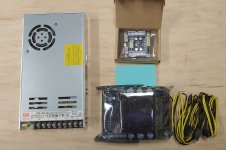
I have been curious about the Wondom JAB5 amp from Sure electronics. It is a 4 channel amp, 4 x 100W, with on board DSP via ADAU1701 DSP. SigmaStudio is used to program this little board. The cost for a JAB5 board, a programming board, a 36V power supply, and miscellaneous cables and connectors is about $160, compared to about $600 for a Hypex Fusion FA253. I am expecting the Hypex to be superior, due to the super-smooth nCore amps and the more sophisticated D/A & A/D processes on the hypex. But I am prepared to be surprised.
This will be a 3 way system with 2 woofers, TMWW. 4 channels for 4 drivers. It will be a tower which positions the tweeter at about 42” high. I want this system to use moderate cost drivers, given the modest cost of the electronics. I have a friend who may want to duplicate this design, and he is a bit sensitive to costs. So no beryllium tweeters, no textreme cones, no scan speak illuminators for this project. I am shooting for a driver cost of about $400 - $500 per side.
== == == == == ==
Update 5/07/2022: Construction has begun, and the design has changed significantly since the first post. https://www.diyaudio.com/community/...3-way-with-twin-8s.378223/page-5#post-7016642
Goals for this project
1) Design and build a complex 3 way system using VituixCad simulation from the start.
2) Build and evaluate a system with optimized DI and a smooth even horizontal dispersion.
3) Explore some new cabinet construction ideas.
4) Have a system which is more portable than my existing system.
5) Have a system which can serve as a backup for my main system.
Index
Construction photos: https://www.diyaudio.com/community/...3-way-with-twin-8s.378223/page-8#post-7048860
Start of Measurement phase (post 167): https://www.diyaudio.com/community/...3-way-with-twin-8s.378223/page-9#post-7058310
Completion of Initial Measurement phase (post 211): https://www.diyaudio.com/community/...-way-with-twin-8s.378223/page-11#post-7065101
Completion of Construction (post 247): https://www.diyaudio.com/community/...-way-with-twin-8s.378223/page-13#post-7085208
Comparison of Simulations to Measured System (post 253)
https://www.diyaudio.com/community/...-way-with-twin-8s.378223/page-13#post-7098334
Final DSP filter (post 260)
https://www.diyaudio.com/community/...-way-with-twin-8s.378223/page-13#post-7103088
Photos of the final project (post 354)
https://www.diyaudio.com/community/...-way-with-twin-8s.378223/page-18#post-7142703
Attachments
Last edited:

In my previous designs [New active Satori Textreme https://www.diyaudio.com/forums/multi-way/352767-active-3-hypex-sb.html], I designed the baffle for minimum edge diffraction by using a large edge radius and bevel. I did not know enough about VituixCad at that time to simulate the full “all axis” response of the systems before I built them.
Over the past several months I have been doing extensive simulations of various baffle shapes, driver sizes, driver arrangement and spacing. The diffraction response of the mid driver and tweeter can combine in ways which either help or hinder the crossover design. A given baffle shape and driver arrangement can make it practically impossible to achieve both a good on-axis response and a good power response, even with ideal drivers, and no matter the crossover techniques. A different combination of baffle and driver arrangement can make it simple to achieve good results. I have come to realize that diffraction is destiny.
I am not sure that a good simulated power response is necessary in my listening room. My room response curve (the “house curve”) seems to correlate much more closely to the simulated listening window than to the simulated power response. However, this speaker is intended not just for me, but for others. So one of my design goals is a good on-axis response and a good power response.
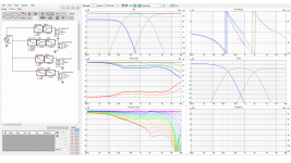
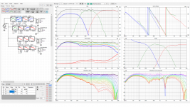
I did a lot of simulations with ideal drivers, and this is the configuration I arrived at: 1181 mm x 305mm (46.5 inch x 12 inch) baffle, 37 mm edge radius on sides and top. A 1 inch tweeter (no waveguide), 5 inch mid, and a pair of 8 inch bass drivers. The attached “6-pack” graphic shows the result. It is interesting how much filter complexity is required even with perfect ideal drivers. This is mostly baffle step compensation, but notice that the crossover from mid to tweeter is non-symmetric: The tweeter has a 1.6k LR4 filter, while the mid has a 2.1k LR4 filter. This causes a phase difference of about 40 degrees, which allows the power curve and the on-axis curve to have a similar shape. These simulated drivers had perfectly flat frequency responses, from 0 – 20 kHz, but their off-axis performance was based on their diameter.
AllenB wrote something in a post a few months ago that really pointed me in the right direction. To paraphrase, it is first important to get the Directivity Index correct. When the DI is correct, EQ can be applied to correct both the on-axis and power response at the same time. That really helped me. I am quite happy that the DI is +/- 0.5 dB from 300 Hz to 6 kHz.
At this point I am looking at feasibility. It seems feasible that with good performing drivers, this baffle shape and layout can be successful.
Over the past several months I have been doing extensive simulations of various baffle shapes, driver sizes, driver arrangement and spacing. The diffraction response of the mid driver and tweeter can combine in ways which either help or hinder the crossover design. A given baffle shape and driver arrangement can make it practically impossible to achieve both a good on-axis response and a good power response, even with ideal drivers, and no matter the crossover techniques. A different combination of baffle and driver arrangement can make it simple to achieve good results. I have come to realize that diffraction is destiny.
I am not sure that a good simulated power response is necessary in my listening room. My room response curve (the “house curve”) seems to correlate much more closely to the simulated listening window than to the simulated power response. However, this speaker is intended not just for me, but for others. So one of my design goals is a good on-axis response and a good power response.
I did a lot of simulations with ideal drivers, and this is the configuration I arrived at: 1181 mm x 305mm (46.5 inch x 12 inch) baffle, 37 mm edge radius on sides and top. A 1 inch tweeter (no waveguide), 5 inch mid, and a pair of 8 inch bass drivers. The attached “6-pack” graphic shows the result. It is interesting how much filter complexity is required even with perfect ideal drivers. This is mostly baffle step compensation, but notice that the crossover from mid to tweeter is non-symmetric: The tweeter has a 1.6k LR4 filter, while the mid has a 2.1k LR4 filter. This causes a phase difference of about 40 degrees, which allows the power curve and the on-axis curve to have a similar shape. These simulated drivers had perfectly flat frequency responses, from 0 – 20 kHz, but their off-axis performance was based on their diameter.
AllenB wrote something in a post a few months ago that really pointed me in the right direction. To paraphrase, it is first important to get the Directivity Index correct. When the DI is correct, EQ can be applied to correct both the on-axis and power response at the same time. That really helped me. I am quite happy that the DI is +/- 0.5 dB from 300 Hz to 6 kHz.
At this point I am looking at feasibility. It seems feasible that with good performing drivers, this baffle shape and layout can be successful.
Attachments
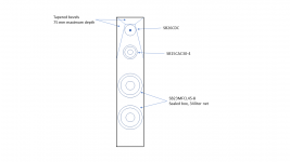
Popular SB_Acoustics aluminum cone drivers are praised for clean, detailed sound.
All Aluminum cone drivers
SB26ADC-4 1" Aluminum Dome Tweeter $55
SB17BAC35-4 6.2" Aluminum cone midbass sealed $77
SB23BAC45-8 8" Aluminum cone woofer can be sealed&equalized or ported 2@ $115
===
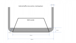
I sketched a Front Baffle with top quarter round routed edges which extends above the rectangular box.
Easier to cut and edge-route a round-top baffle than to build an entire spherical top cabinet.
All Aluminum cone drivers
SB26ADC-4 1" Aluminum Dome Tweeter $55
SB17BAC35-4 6.2" Aluminum cone midbass sealed $77
SB23BAC45-8 8" Aluminum cone woofer can be sealed&equalized or ported 2@ $115
===
I sketched a Front Baffle with top quarter round routed edges which extends above the rectangular box.
Easier to cut and edge-route a round-top baffle than to build an entire spherical top cabinet.
Attachments
Interesting project from the look of the simulations it will sound quite different to your other speakers. The shape of the directivity reminds me of the magico A5 except they have shelved down the on axis.
http://https://www.audiosciencereview.com/forum/index.php?threads/magico-a5-spinorama-cea2034.23866/
I think the listening window and PIR green and orange curves are the most useful in gauging how the speaker will sound in room.
A waveguide or large face plate tweeter might help to stop the sudden rise in directivity at the high end or a faceted baffle.
If cost is really important I would suggest the Zaph ZA14 for the mid, Dayton RS225 for the woofers. The ZA14 is a really excellent mid.
Or for something more interesting, FaitalPro mids and maybe woofers, but I don't have any first-hand experience with those.
Or for something more interesting, FaitalPro mids and maybe woofers, but I don't have any first-hand experience with those.
Hi Jim, nice! If you ever have time to post more on you findings and insight regarding the interplay between baffle size, drivers and their locations, please do!
Many questions, like why did you endup with 12" wide baffle and not as slim as possible? sound reasons or something else like ease of build? it is DSP after all so bafflestep is easily compensated per driver etc. Anyway, while the project is very interesting I suspect you have had much discoveries and fun time behind the scene which I find even more interesting than a particular outcome. So please don't shy out posting any of it, thanks! 🙂
Many questions, like why did you endup with 12" wide baffle and not as slim as possible? sound reasons or something else like ease of build? it is DSP after all so bafflestep is easily compensated per driver etc. Anyway, while the project is very interesting I suspect you have had much discoveries and fun time behind the scene which I find even more interesting than a particular outcome. So please don't shy out posting any of it, thanks! 🙂
Similar to Linesource - An active version of Jeff Bagby / Javad Shadzi’s Ceramicos with the SB ceramic drivers, 2x23CAC + 15CAC + 26CDC would be a pretty good starting point. The original design was approx 2cu.ft and sealed. Details on the DIY Loudspeaker Pad Facebook page or I think there is a kit available. If you get the right combination of wood then the white drivers can be made a feature a la Revel speakers.
Over the past several months I have been doing extensive simulations of various baffle shapes, driver sizes, driver arrangement and spacing. The diffraction response of the mid driver and tweeter can combine in ways which either help or hinder the crossover design. A given baffle shape and driver arrangement can make it practically impossible to achieve both a good on-axis response and a good power response, even with ideal drivers, and no matter the crossover techniques. A different combination of baffle and driver arrangement can make it simple to achieve good results. I have come to realize that diffraction is destiny.
At this point I am looking at feasibility. It seems feasible that with good performing drivers, this baffle shape and layout can be successful.
Hello Hifijim,
Did you include vertical directivity also in your simulated project ? I think it could change a lot results you are showing.
hifijim, I learned recently that the impedance graph on the VituixCAD six-pack can be changed to show the vertical polars! Right click on it and you'll find your way.
Try a GRS PR2522C planar tweeter with a waveguide, Faital Pro 5FE100 mid, and dual Peerless NE180W-8 woofers (poor man’s satori 🙂 )
Check out what the GRS can do in a shallow waveguide: What’s On the Bench Tonight (OBT)
Check out what the GRS can do in a shallow waveguide: What’s On the Bench Tonight (OBT)
I actually decided on my drivers about a week ago. I have been so pleased with the SB "CAC" series of drivers I used in my first build, I am staying with those. SB15CAC30 and SB26CDC.
I had a thread from a couple of weeks ago which clarified my thoughts on the woofer. [ ScanSpeak 22W8534G vs SB23NRXS45-8 vs ? ] This is a sealed box system, with a Linkwitz Transform, so I decided to go with drivers which have good Xmax and power capability. I am using the SB23MFCL45-8.
Given the global supply chain issues, I ordered the drivers much earlier than I need them. They arrived yesterday.
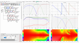
VituixCad2 has the capability of tracing OEM curves and applying the simulated baffle diffraction effect, and I used this capability for the first time. What I find interesting is that the filter based on ideal drivers worked pretty well with the OEM curves. A bit of adjustment and it looked quite good. Most importantly, the DI is very similar between the ideal driver simulation and the OEM-traced-curve simulation. This fact lead me to the revelation that "diffraction is destiny"...
The baffle layout is not finalized, but I like the 12" baffle. It simulates well with a 1.8k - 2k crossover, which is where I want this crossover to be. It also allows the bass drivers to fit on the baffle... After I route a 37 mm radius, the baffle is only 9" wide.
I might go with a side-side woofer config like LineSource shows. If I do that the baffle can be narrower, but the simulation changes, and it appears that the crossover frequency would need to be higher... this is based on a modest level of modelling, I did not spend a lot of time on it.
Thank you for everyone's thoughts. "Progress is a team sport"
j.
I had a thread from a couple of weeks ago which clarified my thoughts on the woofer. [ ScanSpeak 22W8534G vs SB23NRXS45-8 vs ? ] This is a sealed box system, with a Linkwitz Transform, so I decided to go with drivers which have good Xmax and power capability. I am using the SB23MFCL45-8.
Given the global supply chain issues, I ordered the drivers much earlier than I need them. They arrived yesterday.
VituixCad2 has the capability of tracing OEM curves and applying the simulated baffle diffraction effect, and I used this capability for the first time. What I find interesting is that the filter based on ideal drivers worked pretty well with the OEM curves. A bit of adjustment and it looked quite good. Most importantly, the DI is very similar between the ideal driver simulation and the OEM-traced-curve simulation. This fact lead me to the revelation that "diffraction is destiny"...
VituixCad2 simulates the horizontal and vertical response of the system, and this feeds into the power response, the PIR, the ER, etc. Is that what you are getting at?Did you include vertical directivity also in your simulated project ? I think it could change a lot results you are showing.
Many questions, like why did you endup with 12" wide baffle and not as slim as possible?
The baffle layout is not finalized, but I like the 12" baffle. It simulates well with a 1.8k - 2k crossover, which is where I want this crossover to be. It also allows the bass drivers to fit on the baffle... After I route a 37 mm radius, the baffle is only 9" wide.
I might go with a side-side woofer config like LineSource shows. If I do that the baffle can be narrower, but the simulation changes, and it appears that the crossover frequency would need to be higher... this is based on a modest level of modelling, I did not spend a lot of time on it.
Thank you for everyone's thoughts. "Progress is a team sport"
j.
Attachments
...This fact lead me to the revelation that "diffraction is destiny"..
Yeah, no escape from it! It is all about wavelengths, size of the radiators and the environment they are in. Yes, the transducers dont't have ideal radiation above they start narrowing but one doesn't use that part much other than with the tweeter which might be 1" or less, above 10k! The physical acoustic system is what makes the measurements good and allows crossover to split the signal in electronic domain so that it combines back nicely in the acoustic domain. Good drivers on a good physical construct and the result should be gold when the designer knew what the goal should be!🙂
I actually decided on my drivers about a week ago. I am using the SB15CAC30 and SB26CDC and two SB23MFCL45-8. j.
The greater dynamics and higher SPL_max of a 6" SB17CAC35-4 midrange seems a better match to two (21mm P-P) SB23MFCL45-8 woofers.
I actually decided on my drivers about a week ago. I have been so pleased with the SB "CAC" series of drivers I used in my first build, I am staying with those. SB15CAC30 and SB26CDC.
I had a thread from a couple of weeks ago which clarified my thoughts on the woofer. [ ScanSpeak 22W8534G vs SB23NRXS45-8 vs ? ] This is a sealed box system, with a Linkwitz Transform, so I decided to go with drivers which have good Xmax and power capability. I am using the SB23MFCL45-8.
Given the global supply chain issues, I ordered the drivers much earlier than I need them. They arrived yesterday.
VituixCad2 has the capability of tracing OEM curves and applying the simulated baffle diffraction effect, and I used this capability for the first time. What I find interesting is that the filter based on ideal drivers worked pretty well with the OEM curves. A bit of adjustment and it looked quite good. Most importantly, the DI is very similar between the ideal driver simulation and the OEM-traced-curve simulation. This fact lead me to the revelation that "diffraction is destiny"...
VituixCad2 simulates the horizontal and vertical response of the system, and this feeds into the power response, the PIR, the ER, etc. Is that what you are getting at?
The baffle layout is not finalized, but I like the 12" baffle. It simulates well with a 1.8k - 2k crossover, which is where I want this crossover to be. It also allows the bass drivers to fit on the baffle... After I route a 37 mm radius, the baffle is only 9" wide.
I might go with a side-side woofer config like LineSource shows. If I do that the baffle can be narrower, but the simulation changes, and it appears that the crossover frequency would need to be higher... this is based on a modest level of modelling, I did not spend a lot of time on it.
Thank you for everyone's thoughts. "Progress is a team sport"
j.
Hi,
I am very interested in this project and am looking forward to learn from it given that I have a similar project with same mid and tweeter. 🙂
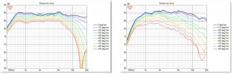
If you are interested in a comparison between the SB26CDC drver horizontal polars between a traced driver on a 30cm wide baffle wth 20mm edge rounding vs the same driver put on a 4 inch elliptical augerpro waveguide on the kind of 30cm wide chamfered baffle (as given in my project thread), please take a look at the attached pic. Left side of the pic shows the traced SPL on 30cm rounded baffle, while right pic are real measurements on my baffle (0 to 90degrees).
Attachments
I have another general doubt. Usually it is said that higher the Q of a filter, the worse will be its time domain performance. That is, the filter will cause more significant ringing in time domain. In our context of linearizing the passband of drivers using parametric EQ, how high of a filter is too much Q, such that it causes audibly worse performance?
I had this doubt while i was trying to do the same in my setup. I see that you have used a Q=3 filter notch filter in the tweeter branch. Hence i thought of asking this question here.
I had this doubt while i was trying to do the same in my setup. I see that you have used a Q=3 filter notch filter in the tweeter branch. Hence i thought of asking this question here.
If the issue being corrected is only from the driver then the high q filter will reverse the issue in the driver and cancel out any ringing. The problem with using high q filters for correction is that they are unlikely to work the same over all off axis angles and can be the result of diffraction etc.
So it depends on what the correction filter is for. Linear time invariant problems can be corrected very precisely but others need a more gentle approach to avoid creating off axis issues.
So it depends on what the correction filter is for. Linear time invariant problems can be corrected very precisely but others need a more gentle approach to avoid creating off axis issues.
If the issue being corrected is only from the driver then the high q filter will reverse the issue in the driver and cancel out any ringing. The problem with using high q filters for correction is that they are unlikely to work the same over all off axis angles and can be the result of diffraction etc.
So it depends on what the correction filter is for. Linear time invariant problems can be corrected very precisely but others need a more gentle approach to avoid creating off axis issues.
Thanks a lot for the reply. 🙂
Could you please provide a bit more insight into how we classify the driver frequency response-related anomalies into LTI or non-LTI types, in general (like is there anything else we can classify into these categories other than baffle diffraction related frequency response anomalies).
Does this also have any implications on the minimum phase-related concepts?
I am asking this since I have heard that minimum phase LTI system and its inverse are causal and stable. Hence I got curious if we are invoking anything related to that by using an inverse kind of filter to correct the driver frequency response anomaly?
Another related question I have is if we measure the driver on a very large/infinite baffle and study its frequency response anomalies and then compare it with the driver frequency response anomalies on the actual final baffle, will we be able to separate out the issues to which the EQ need to be applied (the ones which show up on the infinite baffle response)?
I am sorry if these questions are derailing the objective of this thread.
There is a good description of LTI and response correction in the paper Correcting Loudspeaker Transient Response from David Gunness at Fulcrum Acoustics
Whitepapers | Fulcrum Acoustic
I can't link the paper directly from a phone.
For general IIR parametric EQ I would just measure the driver on the intended baffle and look at the effect of on axis EQ on the off axis responses in vituix. If you can see negative consequences from the on axis EQ then tone it down.
Last edited:
While it is good to have lot of knowledge on how things actually work it is very liberating to tinker with VituixCAD and see the stuff happen even without knowing whats behind, as fluid describes 🙂 For example it is easy to see that certain properties of the response cannot be fixed with EQ and others can be simply by looking a polar graph, or the DI, while tuning an EQ. You'll notice a parametric doesn't have any effect on DI unless EQ is on single driver on crossover region.
I mean, just by tinkering and observing what happens one is able to tune in a very good response, if the physical construct allows very good response. By good I mean smooth DI, in which case the on axis and power response can be smoothed with the EQ. I suspect that with enough hours behind one is able to conect the graphs mentally to the sound so that certain things can be sacrificedforothers. For example a smooth DI seems to yield very good sound, but there might be some reasons to sacrifice the smoothness for even better perceived sound. Anyway, very powerful helper it is for thinking and tweaking. Anyone can come up with very good crossover for a system just by observing, without knowing what phenomenon there is behind all of it, includedbdin the graphs, the acoustic response at location you are observing, the end result!
I mean, just by tinkering and observing what happens one is able to tune in a very good response, if the physical construct allows very good response. By good I mean smooth DI, in which case the on axis and power response can be smoothed with the EQ. I suspect that with enough hours behind one is able to conect the graphs mentally to the sound so that certain things can be sacrificedforothers. For example a smooth DI seems to yield very good sound, but there might be some reasons to sacrifice the smoothness for even better perceived sound. Anyway, very powerful helper it is for thinking and tweaking. Anyone can come up with very good crossover for a system just by observing, without knowing what phenomenon there is behind all of it, includedbdin the graphs, the acoustic response at location you are observing, the end result!
Last edited:
Whitepapers | Fulcrum Acoustic
My latest 3-way uses Hypex FA123, drivers are SB26STAC, 4" Audax HM100Z0 and 2x SS21W (Discovery pulp cone) in closed box. Sorry I don't have high quality measurements, it was wintertime and speakers are too heavy to be carried outdoors...
Speaker design and response tuning is always a compromise and listening is important too. By looking at sims and measurements alone one easily goes to too little details and faults, that don't have any audibility.
DSP units make it easy to do experiments, how gross an EQ setting has to be to be audible. High Q 5dB is hard to hear, but low Q 0.5dB might be heard. Likewise uneven directivity at M/T crossover range gets "averaged" in listening window (CTA2034) and that is real too! Vertical axis problems can be worse, but response can be tuned neutral to listening spot.
Anyway, 3-way with acoustic LR2 or Duelund topology easily gives real hifi sound!
https://www.diyaudio.com/forums/multi-way/321711-avalanche-as1-modernization-2.html#post6521760
- Home
- Loudspeakers
- Multi-Way
- New Project - tower 3-way with twin 8s