Thank you very much i will see what i can do with all these informations.
Bohrok2610 thank you for the lt3094 thermal pad, i did not know it was connected to vin. This tells me lt3042 and 94 were made to be used togheter in a specific layout. But i should just isolate it from the ground plane.
Thank you.
Bohrok2610 thank you for the lt3094 thermal pad, i did not know it was connected to vin. This tells me lt3042 and 94 were made to be used togheter in a specific layout. But i should just isolate it from the ground plane.
Thank you.
Thank you so much. You help was so welcome, now i will use Cset=22u+150k, no Rlim, and i am thinking of using the PGFB divider as the minimum load. Its the best way i think to use less resistors, good idea ?
Because i dont think a single opamp is enough to be in the best current zone for the 3042.
Because i dont think a single opamp is enough to be in the best current zone for the 3042.
Last edited:
He had been asking about the Reference bypass cap..
But anyway yes, it is good to keep to a low value, 4,7 /10uF Output bypass capacitor. I use film, PPS.
Don't you need some ESR in that output cap for stability?
Jan
Linear technology are talking about inductance of the vout node should be a fixed value relative to the output cap.
Jan,
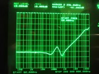
Visibly the LT3042/LT3045 are so fast that the equivalent output inductance do not go in resonance even with low ESR output capacitance.
See scan of the output impedance; the important part is the minimum load current (for the velocity)
here it was 60mA.
Trace 1 is the actual active regulator ootput;
Trace 2 (less bright) is the regulator 'off', so principally one sees the output bypass capacitor..
Attachments

Last edited:
Don't you need some ESR in that output cap for stability?
I've typically used 10uf X7R ceramic capacitors. Never had any stability issues.
Perfect: the more the better.. 🙂
100/200mA..but you do not have headroom left..
If remember well (I had done these measurements in 2020..lockdown..) - then smthing like 30/35 mA could be enough for getting into a usable range. (speed, output impedance)
I keep 50mA as a rule of thumb..
100/200mA..but you do not have headroom left..
If remember well (I had done these measurements in 2020..lockdown..) - then smthing like 30/35 mA could be enough for getting into a usable range. (speed, output impedance)
I keep 50mA as a rule of thumb..
Jan,
Visibly the LT3042/LT3045 are so fast that the equivalent output inductance do not go in resonance even with low ESR output capacitance.
See scan of the output impedance; the important part is the minimum load current (for the velocity)
here it was 60mA.
Trace 1 is the actual active regulator output;
Trace 2 (less bright) is the regulator 'off', so principally one sees the output bypass capacitor..
Yes, I see, these regs are something else.
Very high performance and ease of use.
Jan
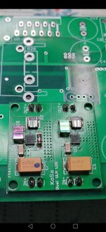
One more thing: the copper area beneath the chip must be large enough for the dissipation. LT30xx are quite robust and the internal power and thermal limiting circuits work well. When these kick in the performance starts to suffer. This performance degradation may however be missed depending on the application.
Yes, I see, these regs are something else.
Very high performance and ease of use.
Jan
Jan, if you are interested I have made a "SilentSwitcher" with LT30xx regulators for high output.
In fact, as it might be seen on my pic, the metal masses are thoroughly connected below/around the tab, 4 almost full layers are taking up/carrying away the heat.
from below a heatsink (20*20mm) could/ should be attached with high dissipation configurations.
from below a heatsink (20*20mm) could/ should be attached with high dissipation configurations.
What is a silentswitcher, is it better than using a center tap tranformer, into the lt3042 and 94 ?
What I refer to "SilentSwitcher" is dual boost/inverter (e.g. LT3471 or LT8582) that generates dual supply from single supply (e.g. 5V in to +-15V out). These output voltages are then regulated with low noise regulator. Jan's original SilentSwitcher uses TPS7Axx regulators. My take on this uses LT3045/LT3094. It has lower lf noise but otherwise not that much better.
- Home
- Amplifiers
- Power Supplies
- Yet another ultra low noise high PSRR LDO - LT3042