Well if he wants to lure people away from his free LTspice to the All New And Improved (ANAI simulator) for a price, that won't be easy.
Jan
Jan
That's what I think in general, even for KiCAD for example.
Why do other companies trying to even bother when LTSpice is basically the de facto standard and otherwise Micro-CAP is for free.
The only improvement that can be made, is to make a better user interface maybe.
Since both programs are very tricky to use from time to time, especially for starters.
So the market and niche you're aiming for is extremely small, yet it requires a ton of work (= money)
I notice that doing a fft on a sine wave source directly only yields a modest THD, unless certain directives are used. One such is ".options plotwinsize=0", but that may still not result in ppm THD?? What else? I also notice that the fft is phase sensitive??
Also, while you can now copy and paste between schematics, the same is not true for symbols, which would be very useful for op-amps, etc. The best trick I have so far is to copy and past text from one *.asy file to another.
Also, while you can now copy and paste between schematics, the same is not true for symbols, which would be very useful for op-amps, etc. The best trick I have so far is to copy and past text from one *.asy file to another.
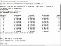
Experimenting with this I found that what matters is maxstep <= 1/freq/1024
.tran 0 {10/freq} {5/freq} {1/freq/1024}
1000 cycles is asking for a very long simulation time and according to the help
"The Fourier analysis is performed over the period from the final time, Tend, to one period before Tend unless an integer Nperiods is given after Nharmonics. If Nperiods is given as -1, the Fourier analysis is performed over the entire simulation data range."
So .tran 0 {2/freq} 0 {1/freq/1024} works OK.
Last edited:
could you perfectly design something in spice that would work? or are simulators not an exact representation of what the practical example would operate like?
It depends what you are designing. Many designs will work perfectly well designed just in simulation alone.
Where it gets more difficult would be things like the value of resistor needed to get a certain bias current in an output stage. This is because the models for the transistors are a little different to real devices and real devices and all the tolerances they have.
Designing for high frequency such as RF amplifiers would be another area where you would need to rely more on real builds and conventional theory.
For all things you are thinking of, yes, simulation gets you most of the way there... as long as you set the simulation up correctly to allow for things that happen in real circuits. Non perfect power supplies for example.
You can say that you can perfectly design in simulation IF the models you feed to the simulator are a perfect representation of the real thing. There lies the rub!
The sim is just a bunch of math routines that implement stuff like Ohms Law. Feed it perfect models, and out come perfect real circuits. But we don't have perfect models, not even for resistors!
Jan
The sim is just a bunch of math routines that implement stuff like Ohms Law. Feed it perfect models, and out come perfect real circuits. But we don't have perfect models, not even for resistors!
Jan
That totally depends on the order of magnitude one is interested in.But we don't have perfect models, not even for resistors!
Jan
Perfect is a relative concept.
The reason why I am saying this, is because that's also how one should approach a simulator.
Try to understand what the pitfalls and shortcomings are, and try to think in sub-circuit and concept simulations.
The biggest mistake a lot of people make (incl many engineers), is try to simulate an entire circuit.
Clearly, in this context, perfect is NOT a relative concept.
OTOH, your idea to approach simulation is relative, personal only ;-)
Although I do agree that building up the circuit by functional areas rather than the whole thing at a time is better.
And you are also right that a bit of understanding goes a long way to avoid pitfalls!
Jan
OTOH, your idea to approach simulation is relative, personal only ;-)
Although I do agree that building up the circuit by functional areas rather than the whole thing at a time is better.
And you are also right that a bit of understanding goes a long way to avoid pitfalls!
Jan
Last edited:
I've been at several startups who bet the company on SPICE, and won the bet. It's quite a useful tool.
On the other hand, Michaelangelo found his chisels to be useful tools as well. But if you gave me Michaelangelo's chisels, I wouldn't suddenly become able to carve Moses or the Pietà or David.
On the other hand, Michaelangelo found his chisels to be useful tools as well. But if you gave me Michaelangelo's chisels, I wouldn't suddenly become able to carve Moses or the Pietà or David.
Clearly, in this context, perfect is NOT a relative concept.
OTOH, your idea to approach simulation is relative, personal only ;-)
Although I do agree that building up the circuit by functional areas rather than the whole thing at a time is better.
And you are also right that a bit of understanding goes a long way to avoid pitfalls!
Jan
By definition everything is relative.
Can't change the rules of physics, sorry.
Come on, this has nothing to do with physics! If we define the word 'perfect' to mean that it is without flaw, then a perfect model is one without flaw. What does physics have to do with that??
You can have a model that has a flaw and thus is not a perfect model, and you can make the point that perfect models do not exist, and I would agree, but 'perfect' is definitely not relative!
Jan
You can have a model that has a flaw and thus is not a perfect model, and you can make the point that perfect models do not exist, and I would agree, but 'perfect' is definitely not relative!
Jan
could you perfectly design something in spice that would work? or are simulators not an exact representation of what the practical example would operate like?
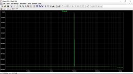
You've gotten some good replies already but at the risk of repeating something it is possible for an actual build to match the performance of a simulation but only if the components in the build exactly match their counterparts in the simulation. Because real parts have tolerances it's unlikely that they will have exactly the values marked on them. Even hand-picked parts will be off by a little.
As an example, attached is the frequency response plot of an op amp based RIAA phono preamp that I designed. The simulation uses a mathematically precise inverse RIAA source so the RIAA components were chosen to precisely match those required to implement the RIAA filter. One might say that the results are "perfect" within the audio band. But I wouldn't expect the measured results to be perfectly flat like this. However, it would expect it to be very close.
In summary: don't strive for "perfection." In engineering, there is such a thing as "good enough."
Attachments

Come on, this has nothing to do with physics! If we define the word 'perfect' to mean that it is without flaw, then a perfect model is one without flaw. What does physics have to do with that??
You can have a model that has a flaw and thus is not a perfect model, and you can make the point that perfect models do not exist, and I would agree, but 'perfect' is definitely not relative!
Jan
Perfect is something exists in fairy tails, not in physics.
Since science is by definition done by statistics, there will be always a certain degree of error, not matter how "accurate" your model is.
Next it has to comply to the Heisenberg uncertainty principle as well.
So any model is imperfect. Not even taking non-linear effects into account.
A "flaw" is only defined by how significant it is inside a certain context.
If this significance isn't relevant for the things one is simulating, it's a perfect model since the flaw isn't relevant.
But on itself, the model is not perfect.
The reason why I am saying all of this, is not to sound silly.
It's trying to explain to people how to make good simulations (of any kind).
Try to determine first how much accuracy one actually need.
Make a little list of priorities, and what could cause errors, than try to divide them in sub-circuits or models that are much easier to simulate.
That way a model can even be very inaccurate, but one can still get very accurate results.
For people who think that is a little far fetched, a real example;
I have seen (and consulting) a whole department who couldn't figure out why their results from an acoustic positioning sensor was so imprecise.
they had all the best oscillators, clocks, ADC's and the whole deal.
Yet, the errors were not created by the system, but by the way they were measuring and determining certain variables and parameters.
So a model can be "super perfect"; garbage in is still garbage out.
These kind of mistakes happen more often than one might think.
I see it all the time.
Issues with simulation are that two real parts are never exactly the same; are not exactly the same temperature, real wires have resistance, inductance and capacitance, and the models are a simplified version of real parts. So it is possible to create a simulated circuit that is impossible to build with real parts. You need to understand that bjt beta and jfet Idss are unpredictable so your circuit must work with a range of parts. In engineering, tolerance "sensitivity" is an important consideration. But if you avoid circuits that have such sensitivities, your results will be very much as like the simulation. Simulation reveals most problems and test ways to avoid them. You need to know which op-amp models model the supply rails properly and which don't. Bad op-amp models will show 100V output from a 15V supply. The results depend on your skill and how much work you put into your models and design. If I was investing a lot of money into a design, I would put more work into the simulation than a I would a quick idea test.
There are ways to simulate temperature changes, device variance (Monte carlo?) or just do a parameter sweep/step, etc.
Accuracy is model dependent and the models seem to be getting better.
Accuracy is model dependent and the models seem to be getting better.
- Home
- Design & Build
- Software Tools
- Installing and using LTspice IV (now including LTXVII), From beginner to advanced