FFT measurements of SuSyLu...
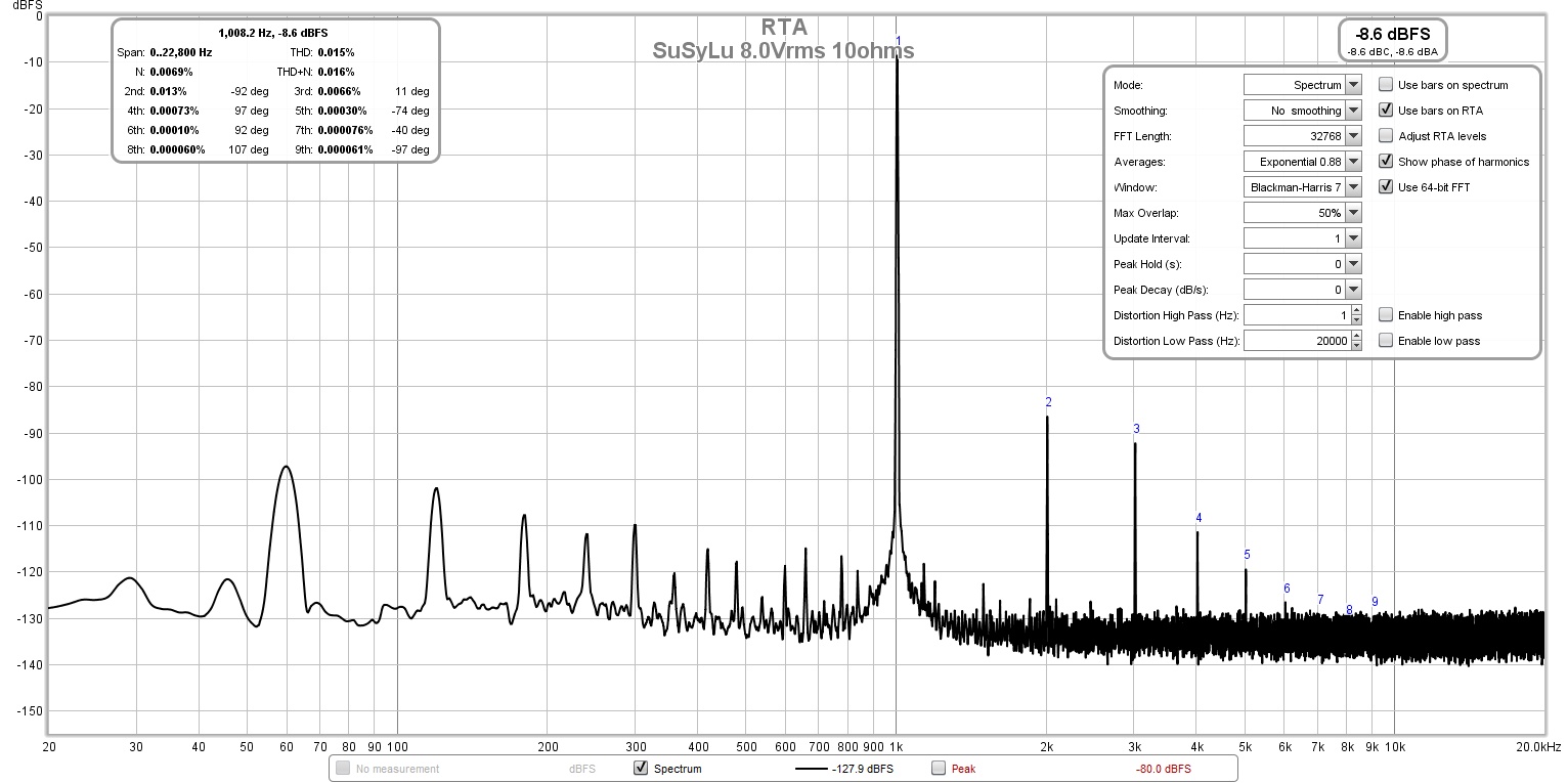
And the measured harmonic profile looks great at 8Vrms or 8w even (THD of 0.015%):
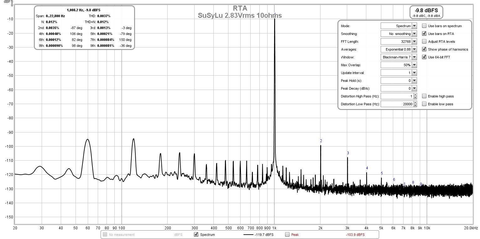
At the reference 2.83vrms, the THD is 0.0037% vs 0.01% for the single LuFo:
At 20Vrms, the profile is starting to switch over to third order dominant:
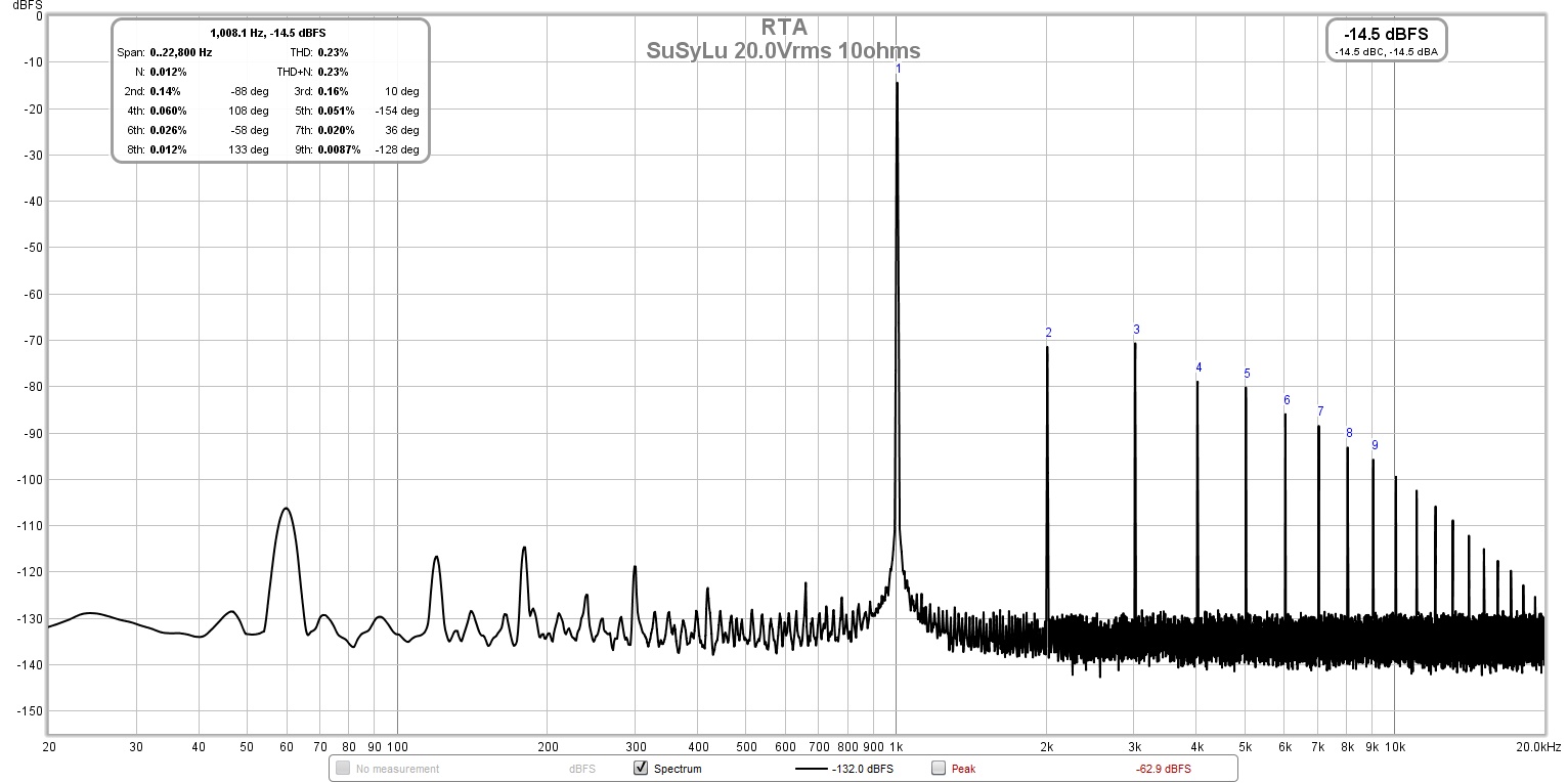
I suspect that the dominant second harmonic is due to imperfect matching of the actives between the two sides.
And the measured harmonic profile looks great at 8Vrms or 8w even (THD of 0.015%):
At the reference 2.83vrms, the THD is 0.0037% vs 0.01% for the single LuFo:
At 20Vrms, the profile is starting to switch over to third order dominant:
I suspect that the dominant second harmonic is due to imperfect matching of the actives between the two sides.
Last edited:
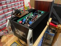
Starting to button up the SuSyLu amp into a real chassis. I really hate chassis work. It takes forever.
A couple of mistakes worthy of Homer Simpson along the way. The soft start board was mounted about 2mm too high because I thought top panel rested on top of the back edge but was in fact flush with it.
In squeezing everything together I think the power trafo is simply too close to the amp. So dealing either with a ground loop or just EMI pick up. But it was 5am when I got to this stage so could not chase it down yet. This may immediately say that the only PSU that can work in a tight chassis like this is a SMPS.
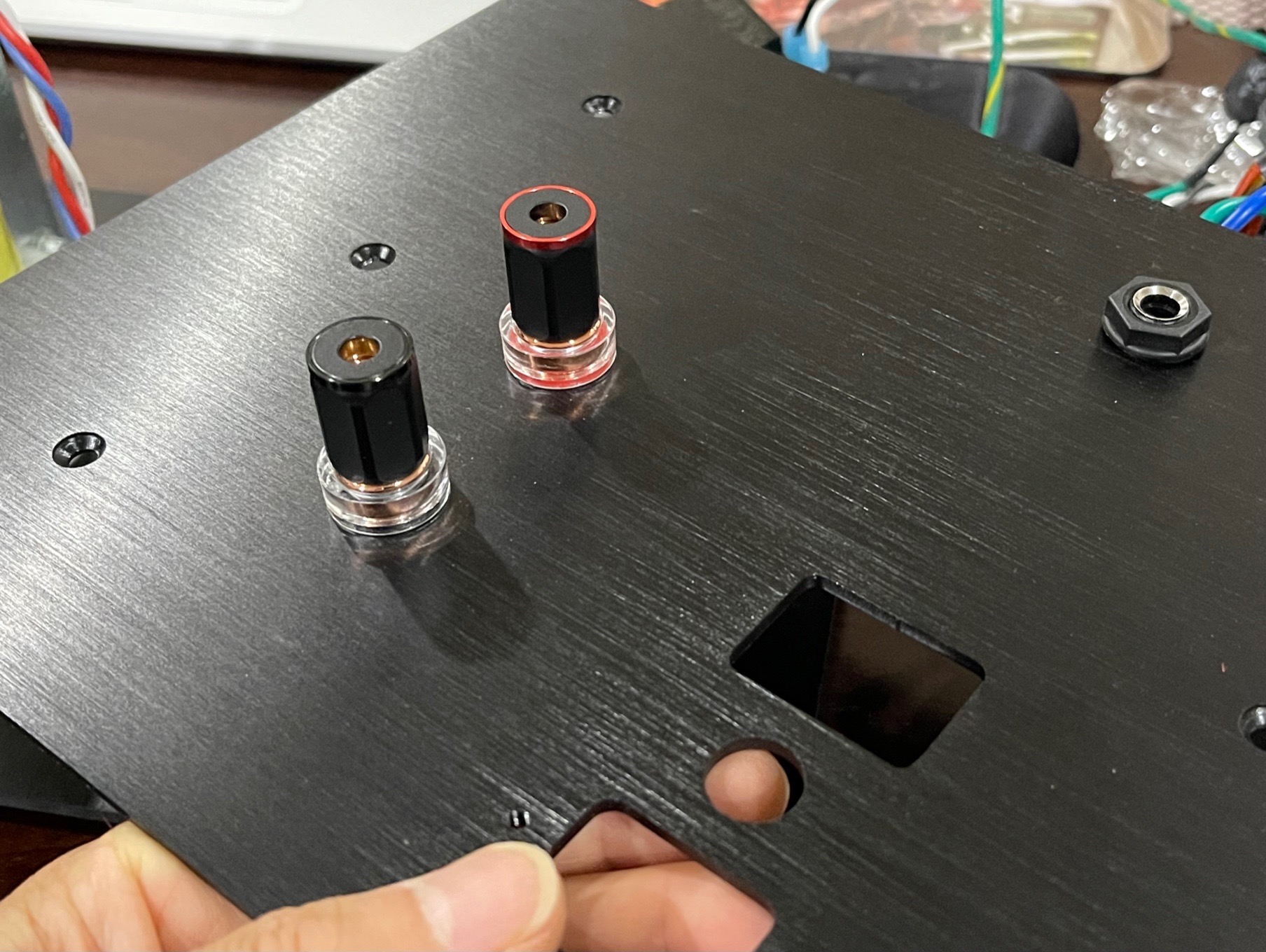
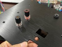
Nice Viborg solid copper binding posts on the back and TRS jack for balanced input. I wanted to install Neutrik XLR but my step drill doesn’t go big enough:
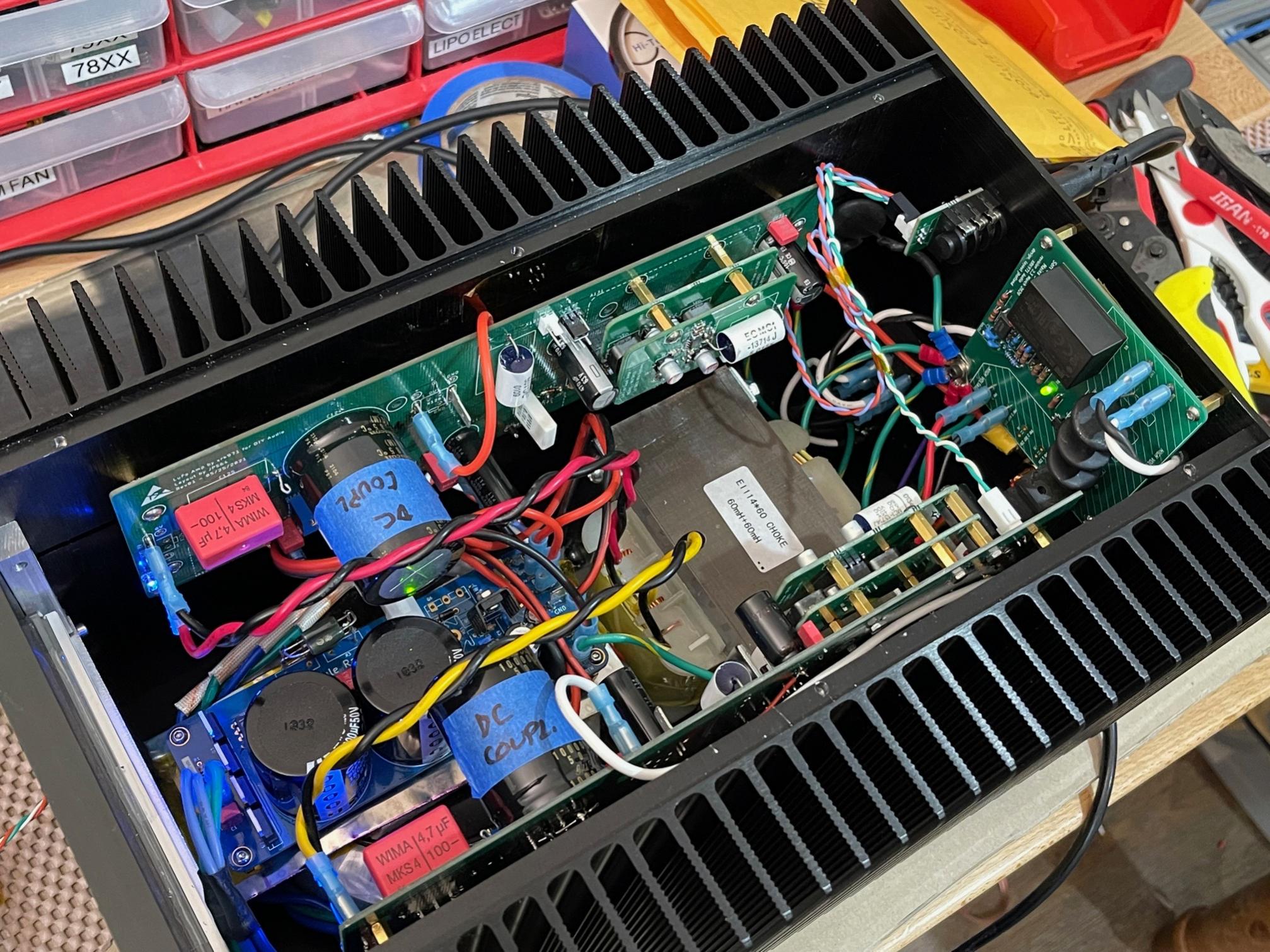
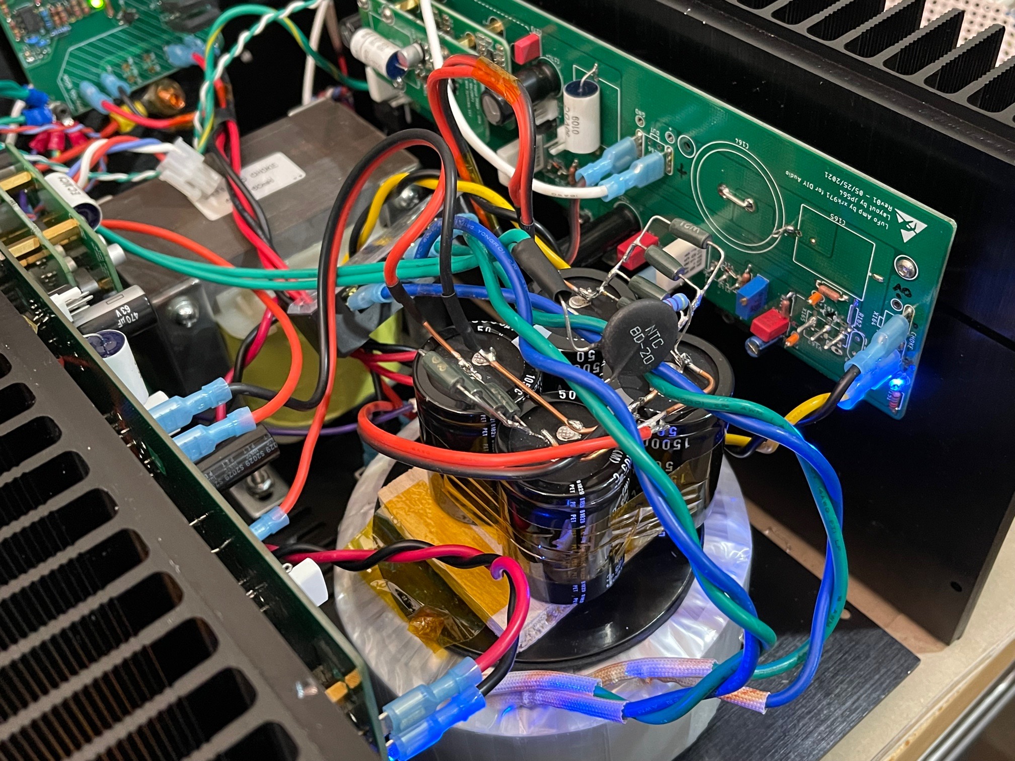
Installing the balanced inductor and SLB pass transistor onto the floorboard which is now a heatsink for about 18w of dissipation from the SLB:

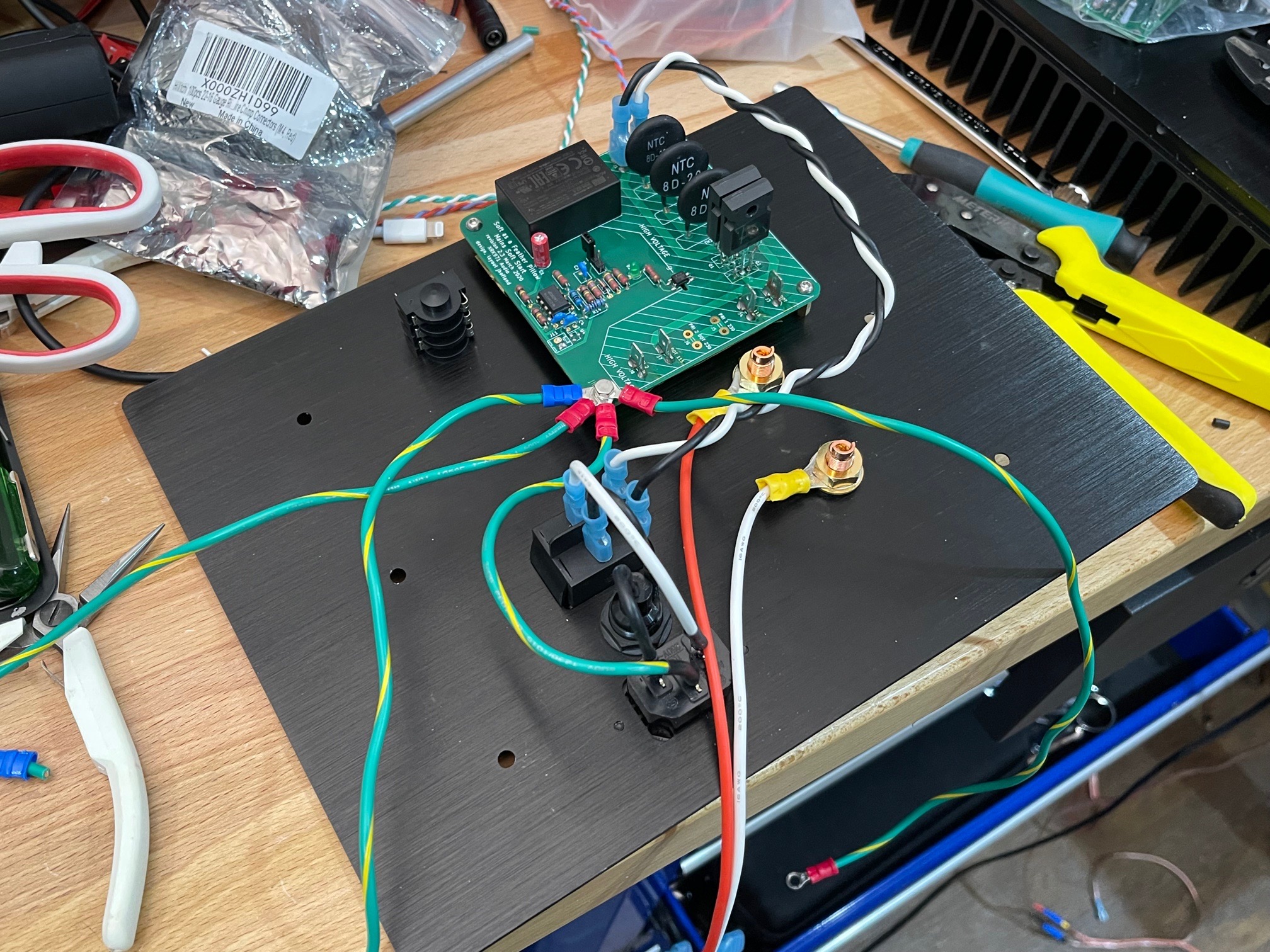
Here is the inside of the rear panel all connected with 16ga silicone insulation wire for the mains hookup and speaker cables. Ground wire is nice industrial green/yellow appliance grade wire. SFP soft start board is mounted oh so nicely, but 2mm too high. Although 2mm lower and it would interfere with the binding post nut:
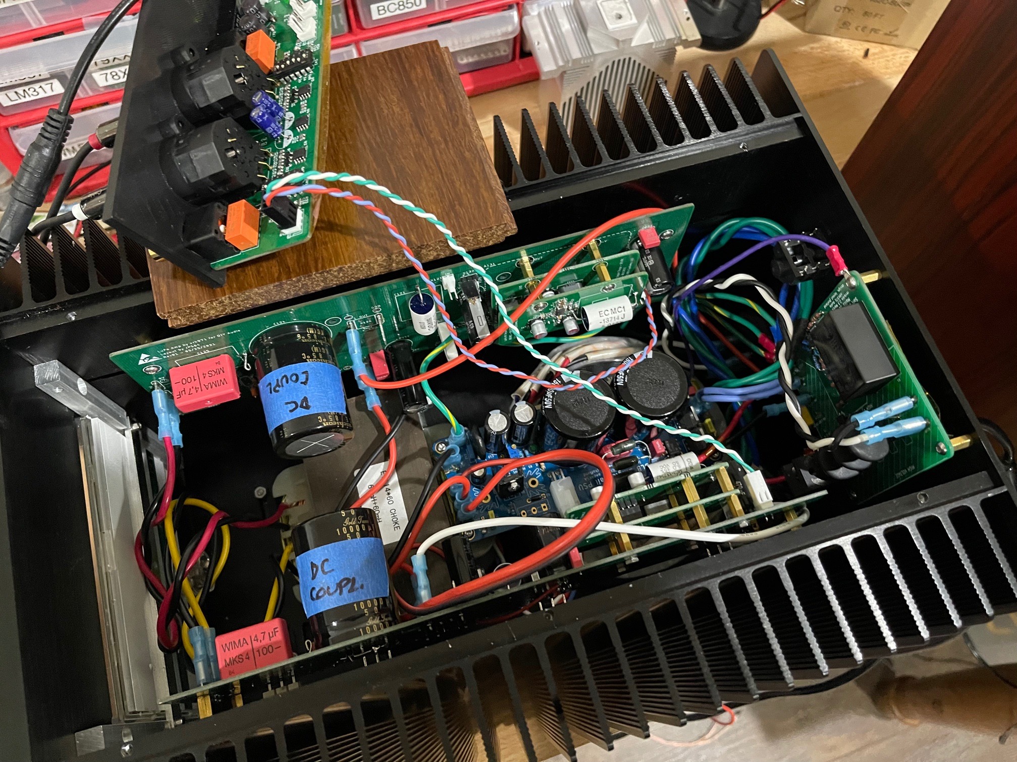
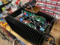
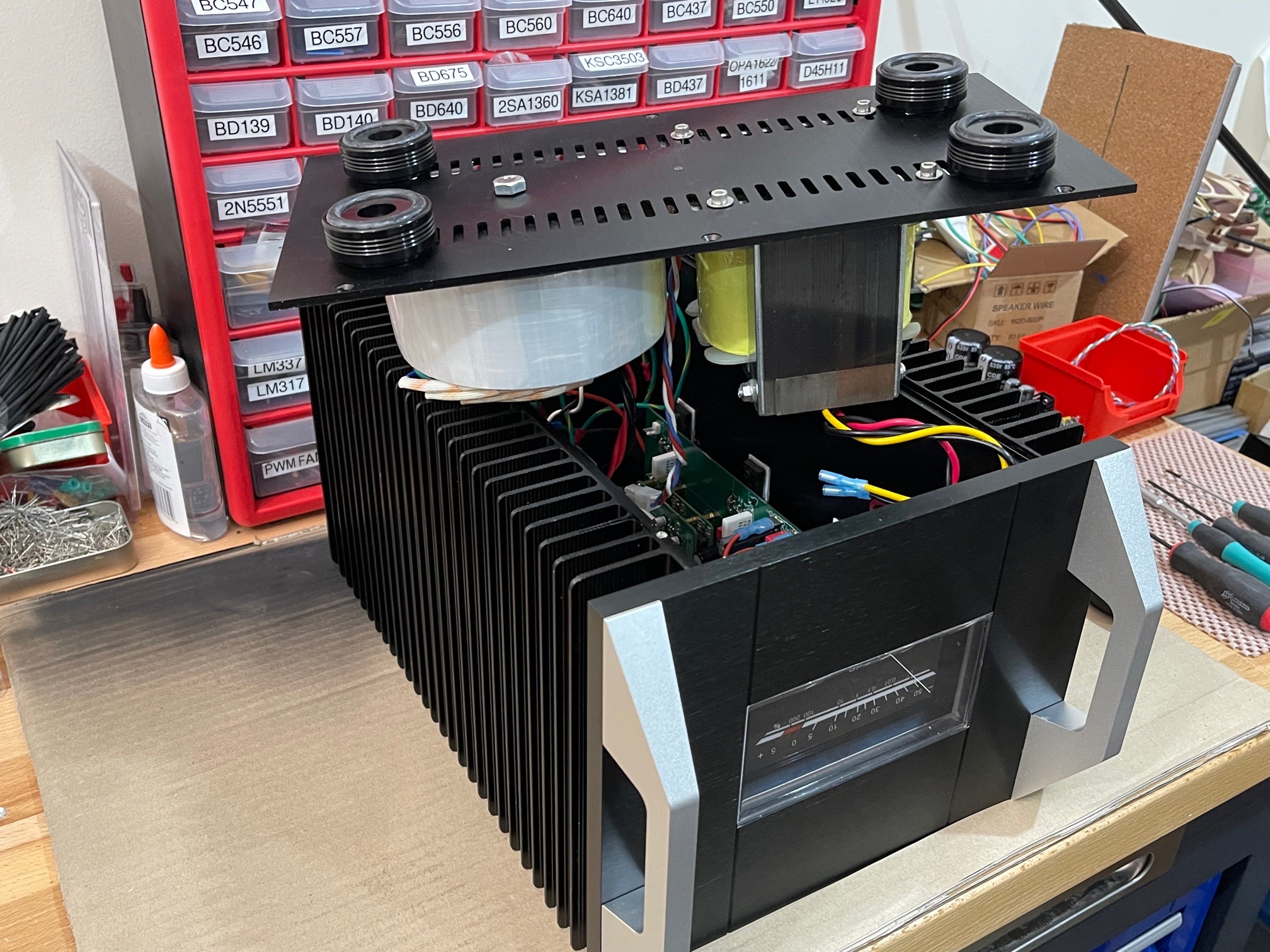
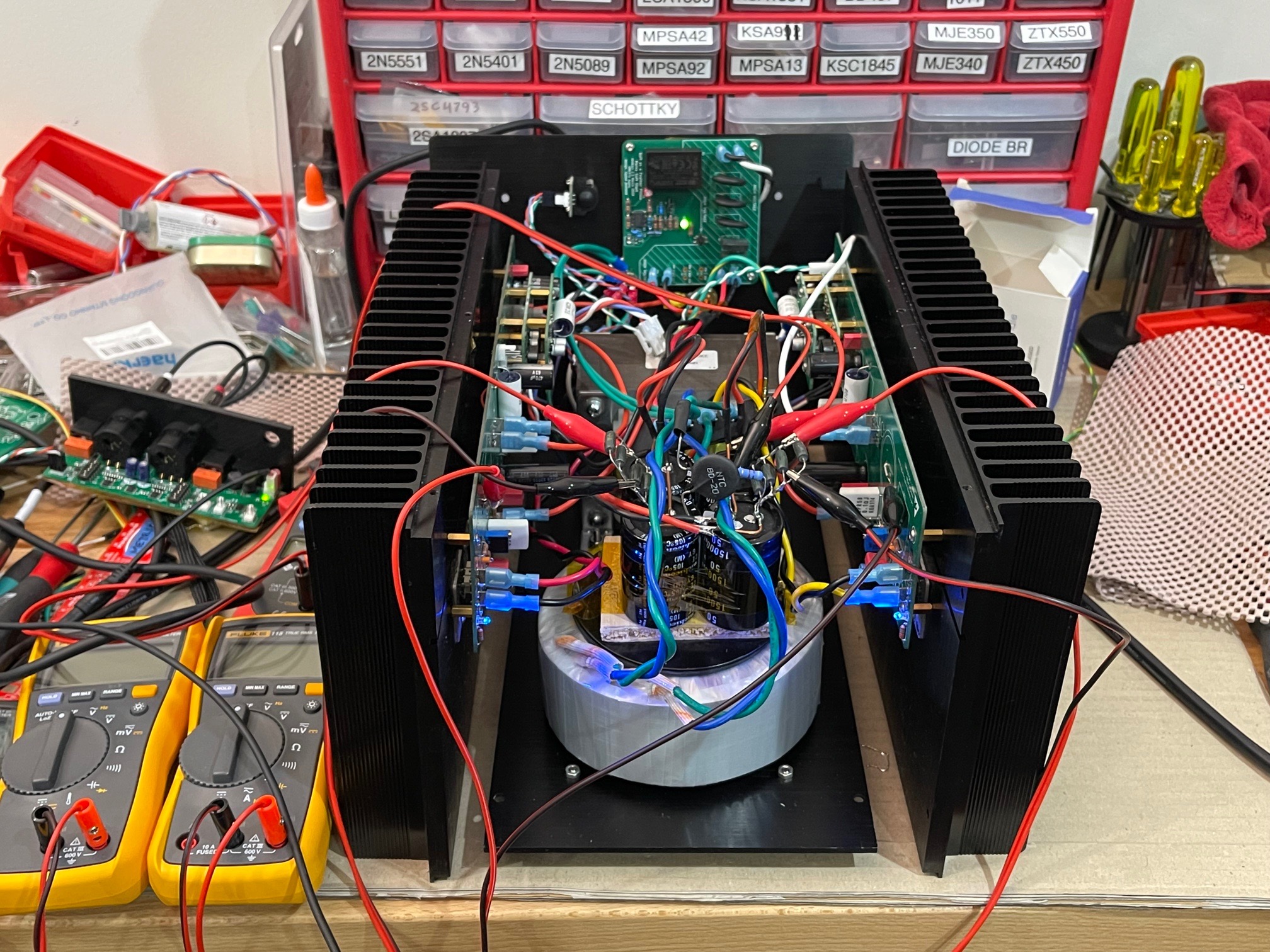
All assembled - the main power trafo is mounted on the floor towards the rear lying flat. The SLB sits on top of it for now. It’s tight. I wish I removed the big output coupled caps (labeled DC coupled) but they would have required a hot air pencil and pulling off the heatsink and I thought maybe leaving them in place let’s me test each leg in SE mode if I remove the jumper. In hindsight, should have removed it:
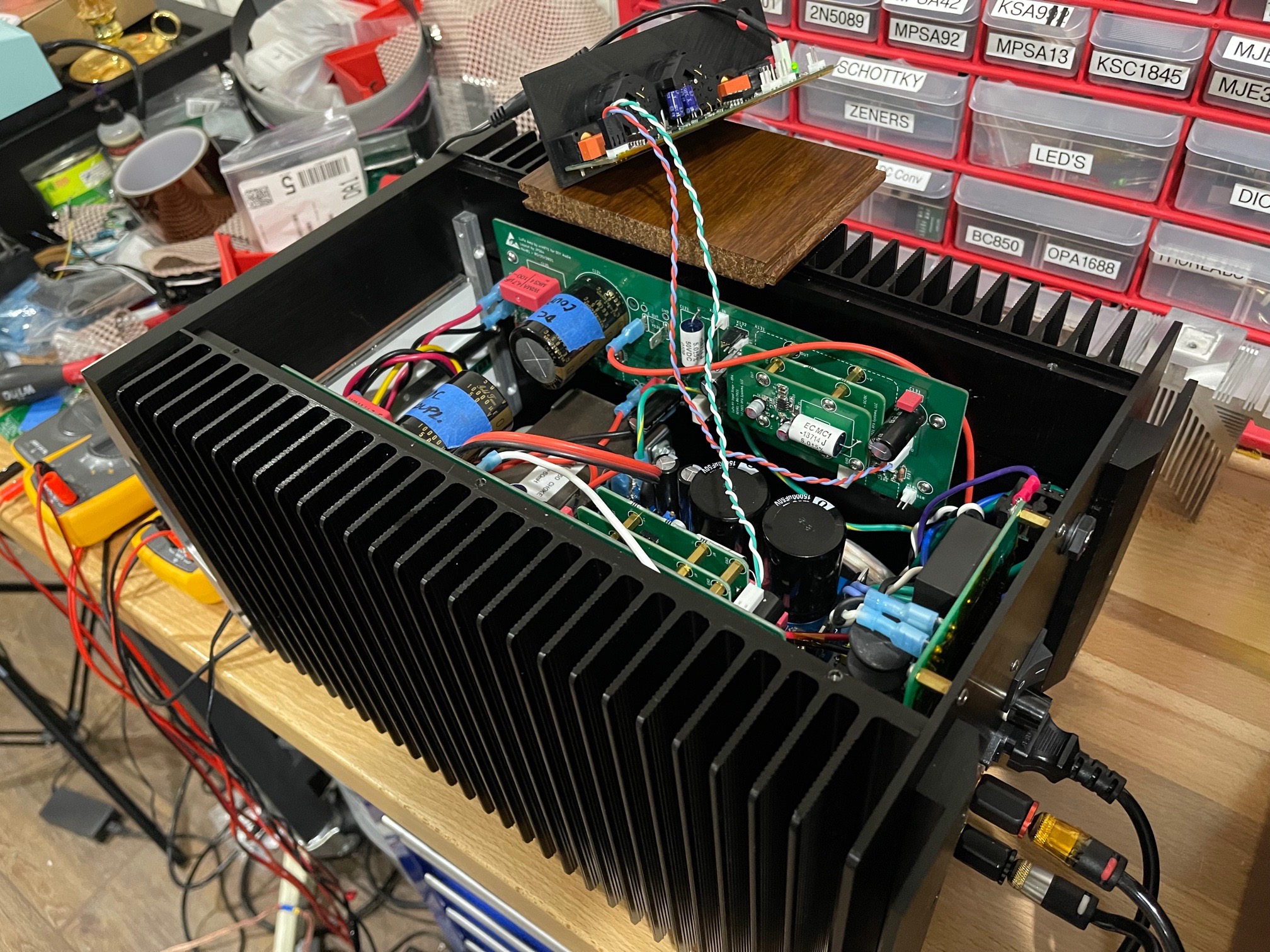
View from to with rear panel:
Front panel but VU meter is not connected yet:

A couple of observations on this build, first thing is that it is massively heavy. I can barely move it and it’s a monoblock. There is no way this could have been done in stereo and be a device that can be transported by one person without rigging or dolly/hand truck. The other thing is that the quality of this CNC chassis is superb. Everything fits together nicely, perfectly aligned (I would say all screws fit within 0.1mm tolerance) and ALL screws for assembly or disassembly are accessible from the outside! I should have taken a photo of the assembly when I lowered the floor plate complete with inductor and trafo down onto the 4 assembled walls. Finally, the build is tight. I still need to put the VU meter board and a RTR SSR speaker protection board in there somewhere.
A couple of mistakes worthy of Homer Simpson along the way. The soft start board was mounted about 2mm too high because I thought top panel rested on top of the back edge but was in fact flush with it.
In squeezing everything together I think the power trafo is simply too close to the amp. So dealing either with a ground loop or just EMI pick up. But it was 5am when I got to this stage so could not chase it down yet. This may immediately say that the only PSU that can work in a tight chassis like this is a SMPS.
Nice Viborg solid copper binding posts on the back and TRS jack for balanced input. I wanted to install Neutrik XLR but my step drill doesn’t go big enough:
Installing the balanced inductor and SLB pass transistor onto the floorboard which is now a heatsink for about 18w of dissipation from the SLB:
Here is the inside of the rear panel all connected with 16ga silicone insulation wire for the mains hookup and speaker cables. Ground wire is nice industrial green/yellow appliance grade wire. SFP soft start board is mounted oh so nicely, but 2mm too high. Although 2mm lower and it would interfere with the binding post nut:
All assembled - the main power trafo is mounted on the floor towards the rear lying flat. The SLB sits on top of it for now. It’s tight. I wish I removed the big output coupled caps (labeled DC coupled) but they would have required a hot air pencil and pulling off the heatsink and I thought maybe leaving them in place let’s me test each leg in SE mode if I remove the jumper. In hindsight, should have removed it:
View from to with rear panel:
Front panel but VU meter is not connected yet:
A couple of observations on this build, first thing is that it is massively heavy. I can barely move it and it’s a monoblock. There is no way this could have been done in stereo and be a device that can be transported by one person without rigging or dolly/hand truck. The other thing is that the quality of this CNC chassis is superb. Everything fits together nicely, perfectly aligned (I would say all screws fit within 0.1mm tolerance) and ALL screws for assembly or disassembly are accessible from the outside! I should have taken a photo of the assembly when I lowered the floor plate complete with inductor and trafo down onto the 4 assembled walls. Finally, the build is tight. I still need to put the VU meter board and a RTR SSR speaker protection board in there somewhere.
Attachments
-
 2AC7187E-84FD-44A4-86C9-D2A0EE7EF983.jpeg557.6 KB · Views: 872
 -
 BFF807CE-8487-4F6A-96F6-B649DF8E312C.jpeg914 KB · Views: 849
 -
 1271922C-0B47-4235-A778-A8F142F03644.jpeg936.6 KB · Views: 475
 -
 7EAD53B5-B2A2-4BC1-B478-87D563F0F9EF.jpeg930.4 KB · Views: 874
 -
 6B34A4E1-BC03-43B4-B750-84038AA931B4.jpeg897.1 KB · Views: 887
 -
 693ED7B3-C3F0-4FA1-9E08-CBCD8C3E6121.jpeg575.4 KB · Views: 855
That is looking phenomenal - congrats . A finished product worthy of the effort put into the design and testing.  ..dB
..dB
..dBFantastic progress X!
Hopefully you don’t suffer too much today from sleep deprivation, recovery time isn’t what it used to be 😀
Hopefully you don’t suffer too much today from sleep deprivation, recovery time isn’t what it used to be 😀
Well, not quite finished. I need to chase down a ground loop. I may be missing an NTC between chassis and mains earth ground. That was there on the plank amp but not here because I thought the NTC on the SLB was enough. I do note that the LuFo boards themselves don’t have NTC ground loop breakers (which is usually the norm on all JPS64 amp layouts). I’ll try taking the amp apart again and play with grounding. Luckily only 10 externally accessible M4 socket cap screws take all the walls apart and 6 Philips head screws from the bottom drops the floor panel.
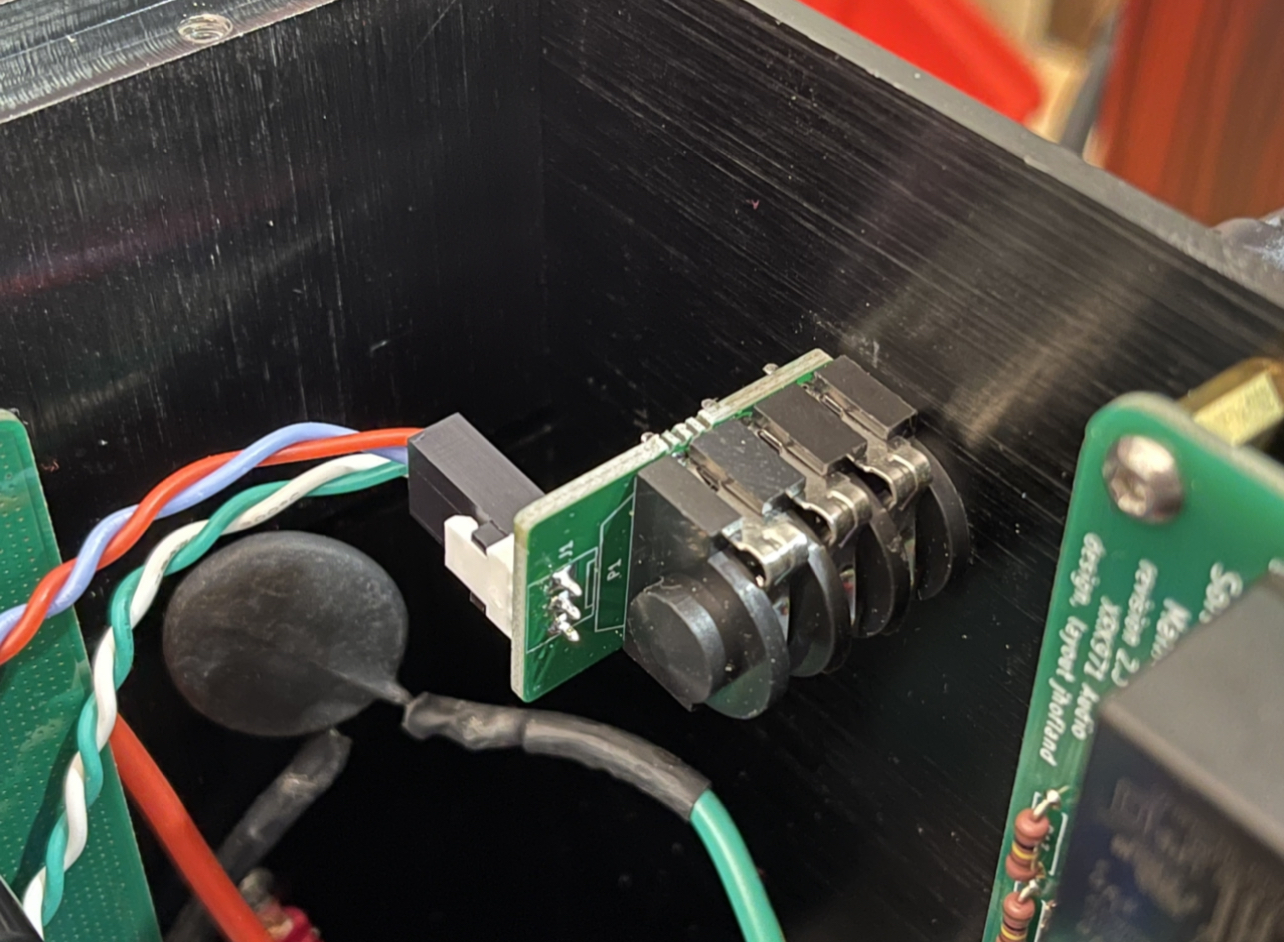
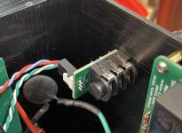
Jhofland made these cute little TRS jack helper boards for me. I hate soldering wires directly to pins on these jacks. They always break from wire strain.
Properly crimped Molex KK connectors are always better for reliability and longevity vs flying leads.
Properly crimped Molex KK connectors are always better for reliability and longevity vs flying leads.
Attachments
Swapped positions of the trafo and inductor 180deg by flipping the floor plate around to see if noise would go down. It helped a little but not enough.
The next step is to take the linear toroidal trafo outside. Maybe a third chassis for the PSU is what is needed.
The next step is to take the linear toroidal trafo outside. Maybe a third chassis for the PSU is what is needed.
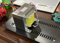
The power trafo is Antek 400VA, and Antek's run on the large side. The custom EI balanced choke is wound on a nominal 600VA core. It is large (11lbs of grain oriented silicon steel (GOSS) wound with bifilar 14ga copper magnet wire for nominal 0.5ohm DCR and 60mH at 10kHz) and oversized on purpose to make sure it doesn't saturate.
A careful study of the source of noise/buzz/hum on SuSyLu was performed in flat plank amp mode. It seems adding a second SLB helps. The location or proximity of the toroidal trafo to the inductor did not matter. The biggest culprit is the ground loop caused by connecting the PSU ground pin at the peripheral of the layout star hub ground. Simply moving that to the physical star hub ground (where speaker out was) solved the majority of the ground loop. The amp is now silent again in this mode flattened, two SLBs, and ground pin location moved. Reassembling to a box may change things die to EMI with other components.
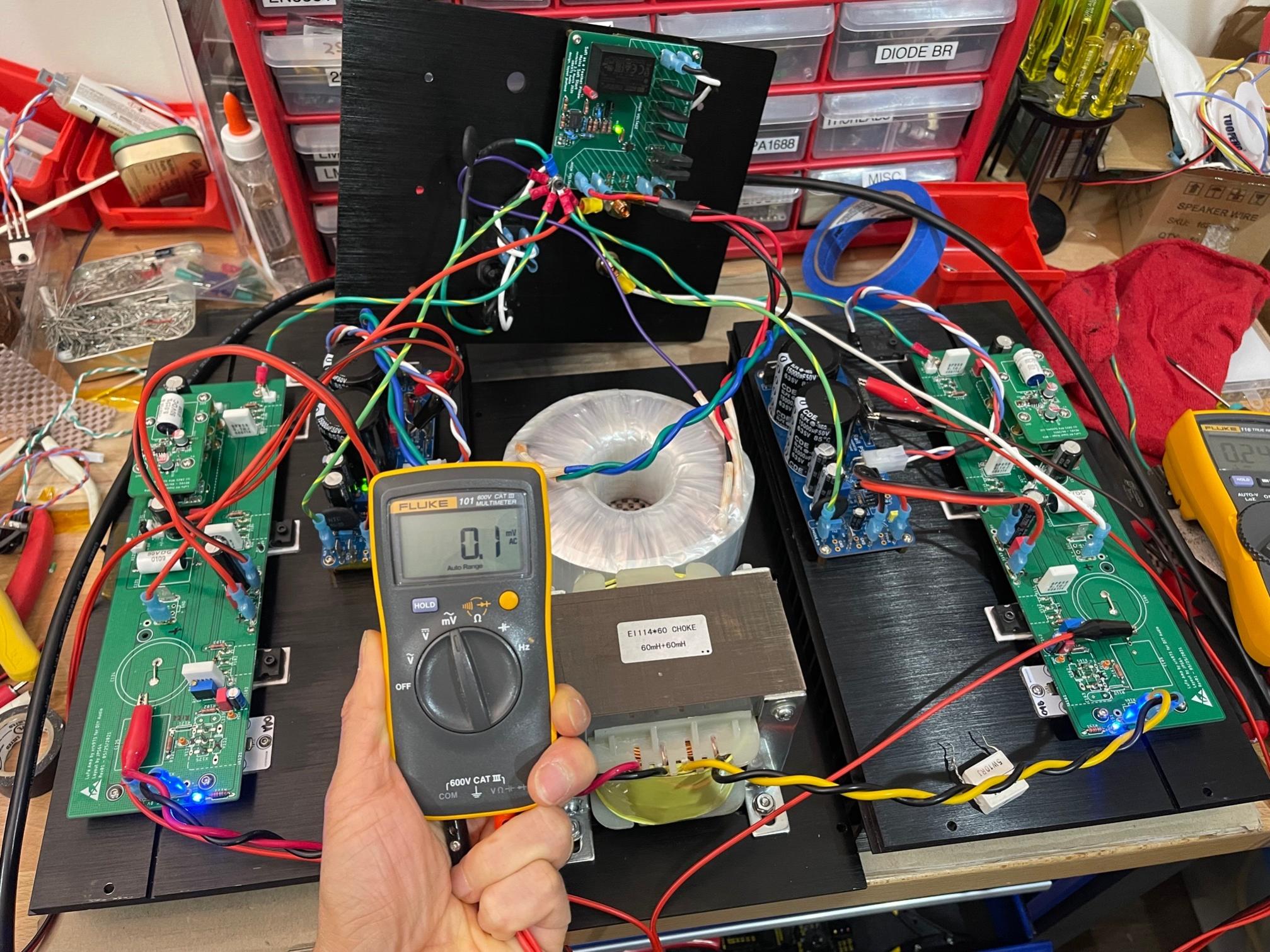
Trafo far apart from inductor reads 0.1mV rms:
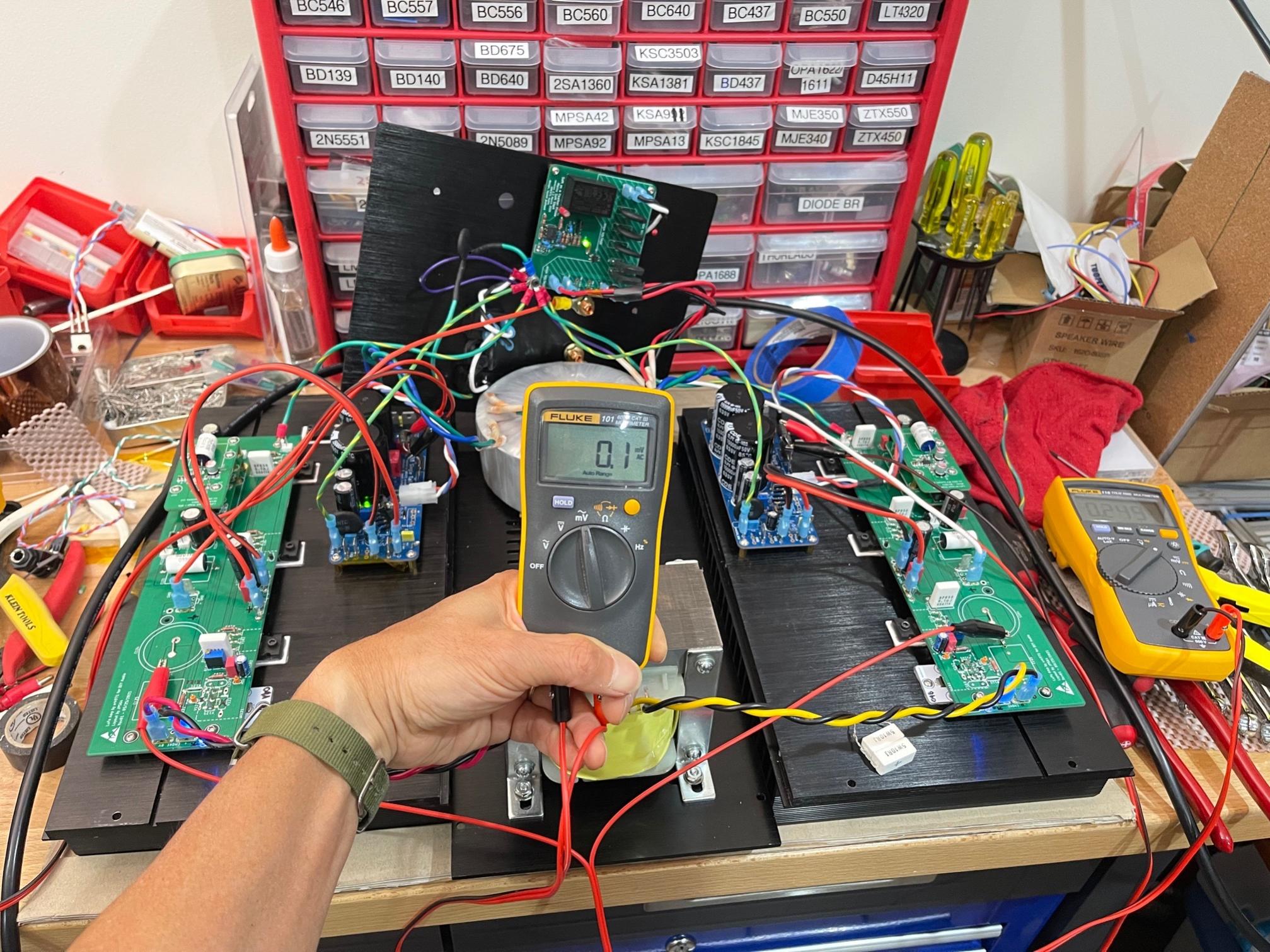
Trafos close together reads the same:
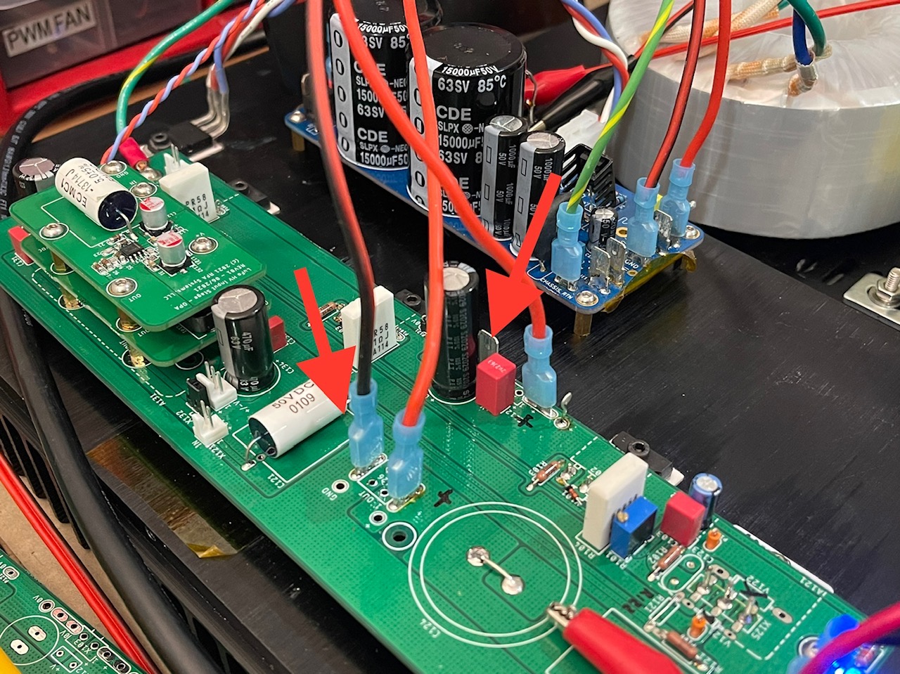
Move the SLB ground pin to the star hub location:
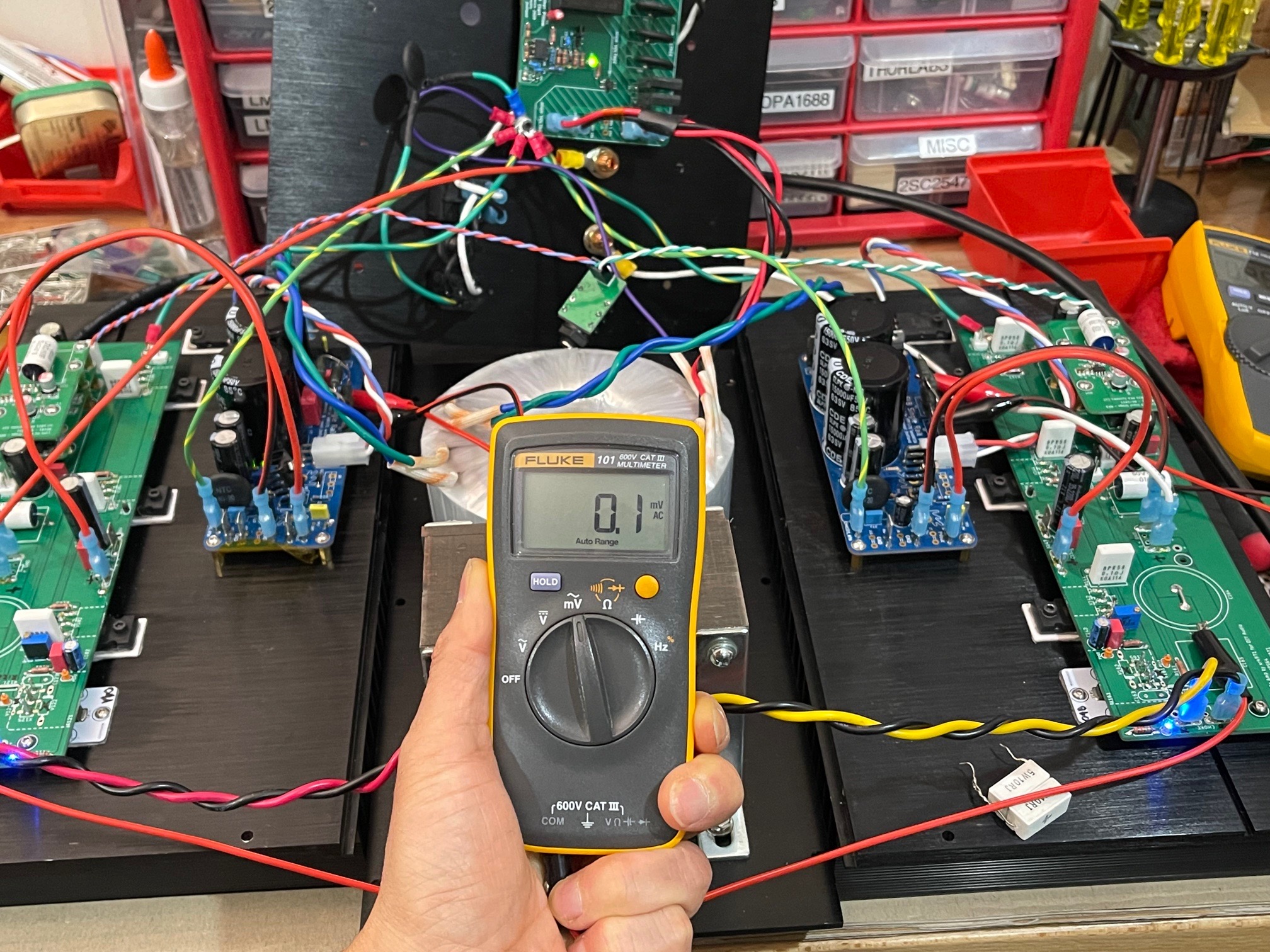
Noise with ground moved to star hub now is quiet at 0.1mV rms (it was in 1.4mV range before):
The Fluke 101 in mV AC mode has unique ability to show what we hear as mains induced hum/buzz/ground loops. If it reads 0.1mV the speakers are silent with ears pressed to cone. I had speakers connected simultaneously in order to debug source of noise as I moved things around. Good news is that location of trafo near inductor did not matter. I was able to move them father apart by more 1in, if that matters.
Trafo far apart from inductor reads 0.1mV rms:
Trafos close together reads the same:
Move the SLB ground pin to the star hub location:
Noise with ground moved to star hub now is quiet at 0.1mV rms (it was in 1.4mV range before):
The Fluke 101 in mV AC mode has unique ability to show what we hear as mains induced hum/buzz/ground loops. If it reads 0.1mV the speakers are silent with ears pressed to cone. I had speakers connected simultaneously in order to debug source of noise as I moved things around. Good news is that location of trafo near inductor did not matter. I was able to move them father apart by more 1in, if that matters.
Last edited:
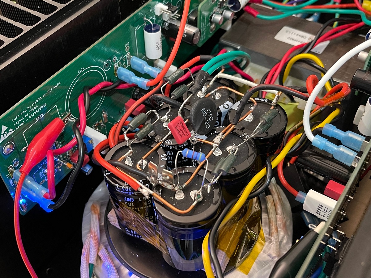
On the bench tonight is a test of the SuSyLu with a basic silicon diode bridge and CRC power supply. 15,000uF // 2x 0.33R 3W in parallel // 15,000uF per leg. With the Antek AS-4224 it’s getting 30v at 3.1A. The amp output at the speaker is pretty quiet at 0.2mV rms. No audible hum with ear 2in away from the speaker cone.
However, the moment I connect the balanced preamp input from the TRS jack, there is ground loop hum. Continuing to debug the ground loop. But it does look like the balanced amp has decent PSRR as a standard CRC appears to be quiet enough.
However, the moment I connect the balanced preamp input from the TRS jack, there is ground loop hum. Continuing to debug the ground loop. But it does look like the balanced amp has decent PSRR as a standard CRC appears to be quiet enough.
Attachments


On the bench last night Sept 30, 2021:
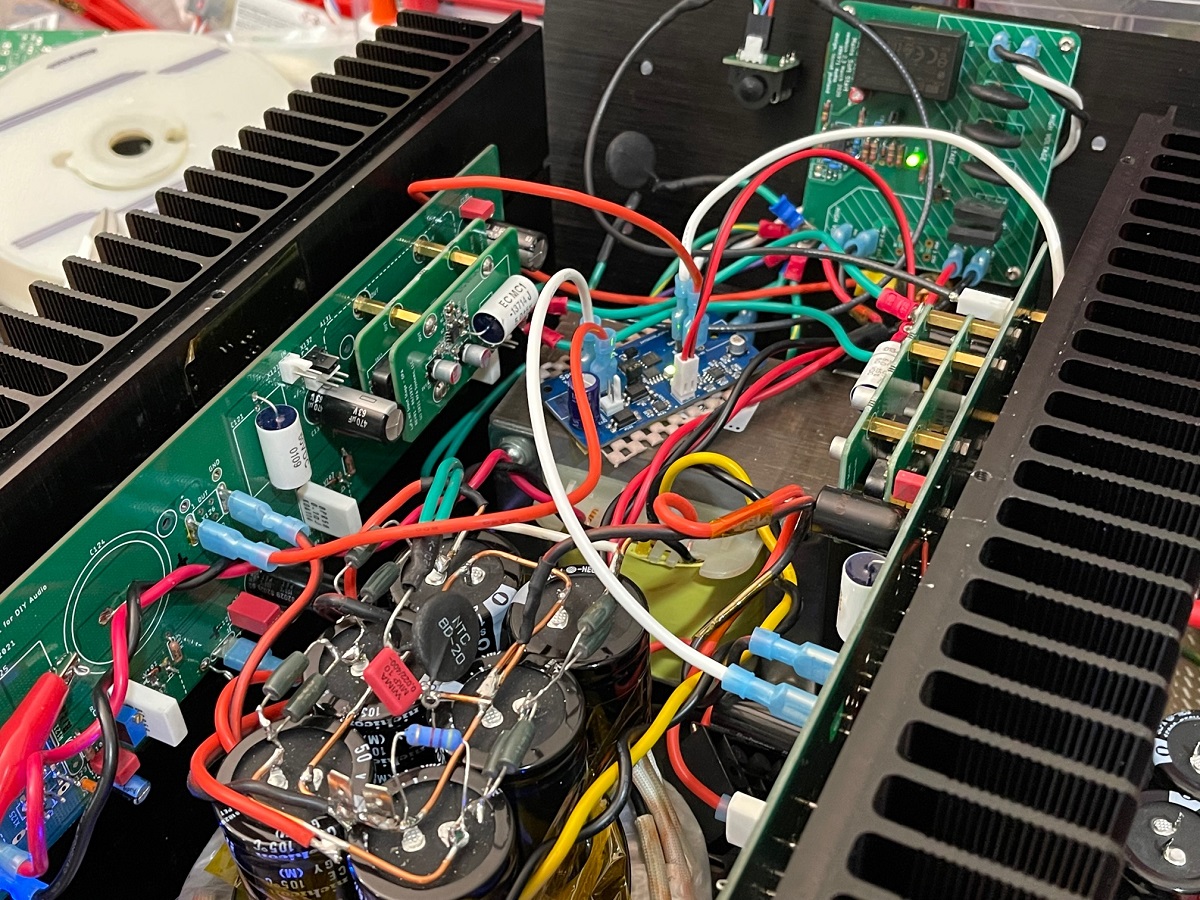
I finally solved the ground loop on the SuSyLu amp. The balanced input nature of the amps means that the output stages need to be driven by a driver stage that has low impedance ground between each opamp (ideally on same PCB). Since the drivers are on the output stage boards as this was adapted from the single ended LuFo, the way to do this is to put a big low impedance ground strap between the two ground bolts on the HV OPA454 daughter boards. I used two 16ga silicone RC race car wires for this. It worked! With a CRC PSU, the hum is gone and output shows 0.2mV rms on Fluke 101. Residual noise is probably just CRC ripple and not audible if ears more than 4-5in from speaker cone.
I finally solved the ground loop on the SuSyLu amp. The balanced input nature of the amps means that the output stages need to be driven by a driver stage that has low impedance ground between each opamp (ideally on same PCB). Since the drivers are on the output stage boards as this was adapted from the single ended LuFo, the way to do this is to put a big low impedance ground strap between the two ground bolts on the HV OPA454 daughter boards. I used two 16ga silicone RC race car wires for this. It worked! With a CRC PSU, the hum is gone and output shows 0.2mV rms on Fluke 101. Residual noise is probably just CRC ripple and not audible if ears more than 4-5in from speaker cone.
When you have a time, your cool diagrams illustrating this would be useful!
Thanks again X for sharing in your diyaudio adventures!
Best,
Anand.
Thanks again X for sharing in your diyaudio adventures!
Best,
Anand.
Been working on a DCC booster for model railways.
It takes in DCC signal and outputs same signal unless a short is detected.
If short detected it lights an LED, makes output signal o/c and waits for reset button to be pressed.
The signal in and out must be exactly aligned as the track will short between them as the loco cross the separator joint.
Seems simple enough.
I started by using a PIC16f753 but it wasnt switching fast enough.
So tried a PIC32mx230 50MHz and that was fine.
It has 2 uses, one is for driving accessories that work off DCC.
And powering remote track.
When you have a time, your cool diagrams illustrating this would be useful!
Thanks again X for sharing in your diyaudio adventures!
Best,
Anand.
Hi Anand,
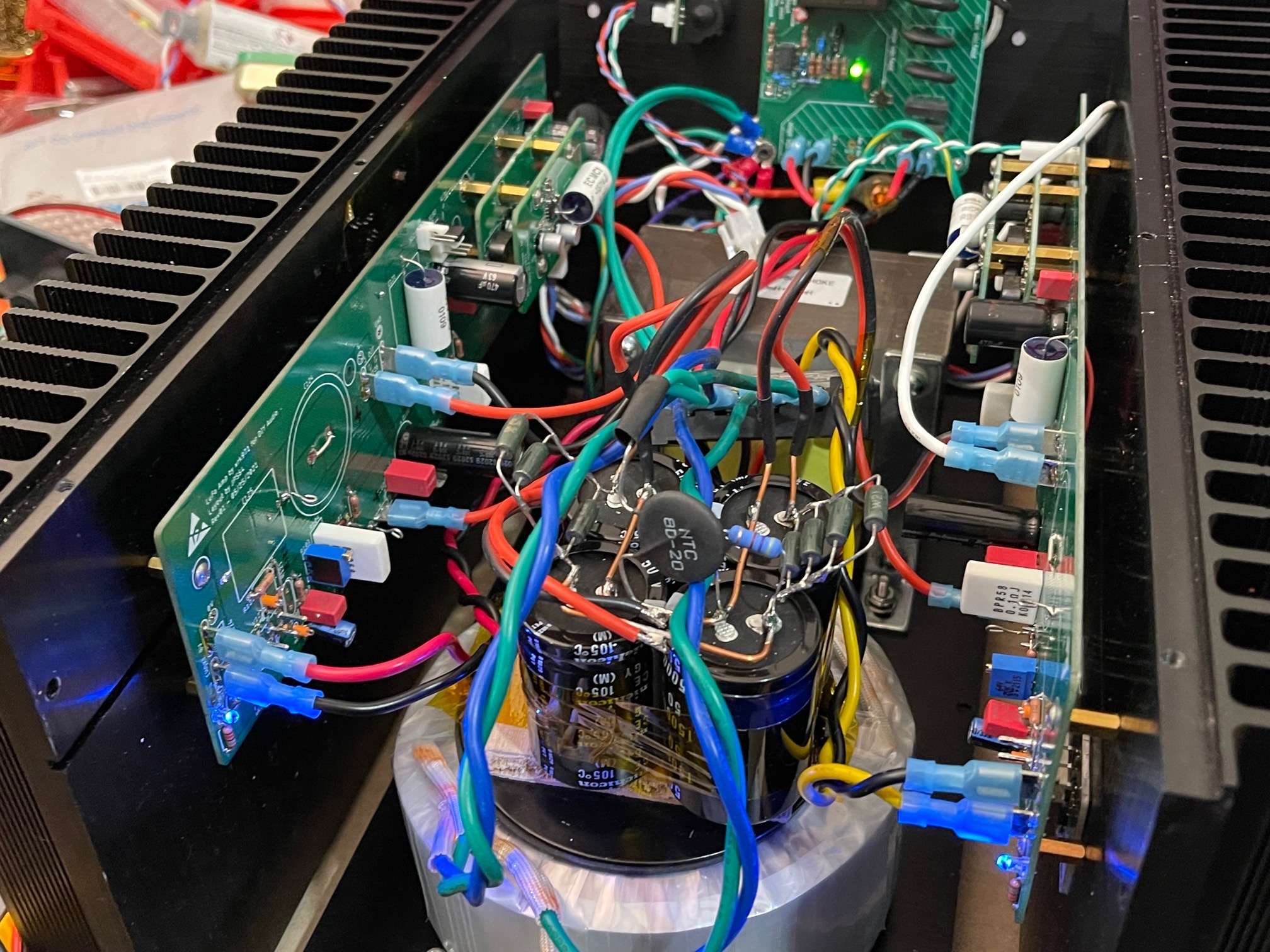
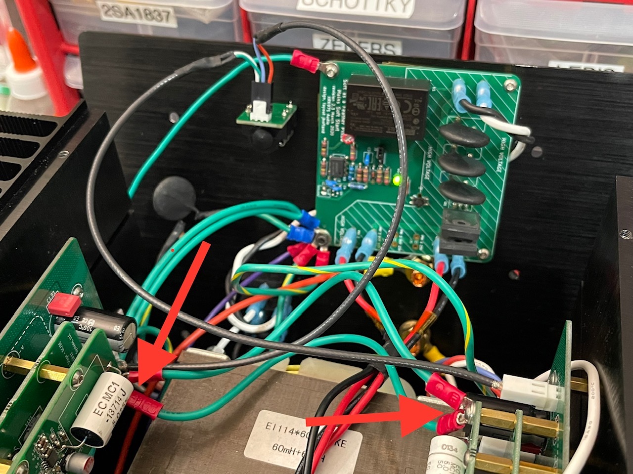
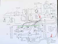
Here is how it is currently hooked up. I am finding out that ideally, the balanced TRS jack shield connection should go to chassis ground and not signal ground as I have it connected. The green ground strap between the two daughterboards was the key thing that fixed the hum.
Attachments
Been working on a DCC booster for model railways.
It takes in DCC signal and outputs same signal unless a short is detected.
If short detected it lights an LED, makes output signal o/c and waits for reset button to be pressed.
The signal in and out must be exactly aligned as the track will short between them as the loco cross the separator joint.
Seems simple enough.
I started by using a PIC16f753 but it wasnt switching fast enough.
So tried a PIC32mx230 50MHz and that was fine.
It has 2 uses, one is for driving accessories that work off DCC.
And powering remote track.
Hi Nigel,
I made a DCC controller using Arduino and a standard “Motor Shield”. Software is all online of course. It worked. But in the end, I plunked down $90 for a prebuilt DCC controller all boxed and ready to use. Much simpler - no chassis or PSU to build. Plus, my 6yr old (at the time) could use it easily.m
There is a huge following of people programming $1 ATTtiny286 (DIP8 RISC MCU’s) as Arduino compatible controllers for doing all sorts of model RR functions for switching tracks, lifting gates, operating draw bridges or blinking custom lights, etc along the track. All self-running once programmed.
Last edited:
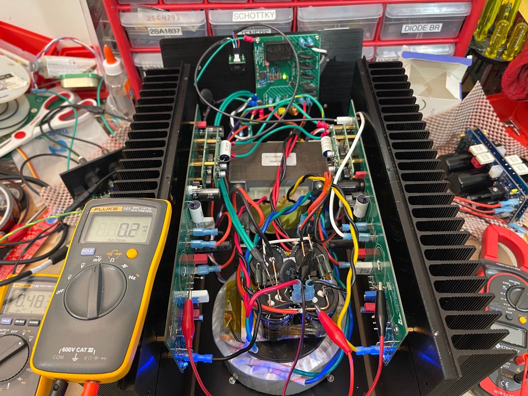
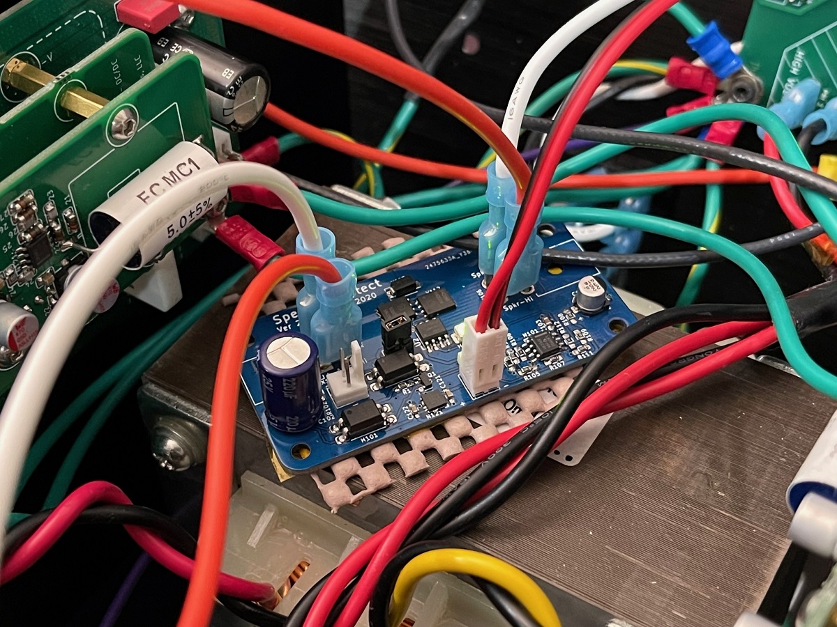
On the bench tonight Oct 1, 2021 is adding a CRCRC power supply to the SusyLu amp. This reduced the supply ripple down to 50mV rms from 100mV rms, however, the amp has pretty good PSRR so the output noise is still 0.2mV rms. I also added my Gen2 SSR DC speaker protection module which can be used with BTL amps where both speaker outputs are "live".
Sound Clips of SuSyLu in main system with a real DAC.
https://www.diyaudio.com/forums/attachment.php?attachmentid=987664&stc=1&d=1633221958
https://www.diyaudio.com/forums/attachment.php?attachmentid=987664&stc=1&d=1633221958