Fired mine up last night for the first time. Bias is holding steady at 14 volts and those fets sure do get hot. Since this is my first foray into class A solid state I'm not used to the heat output. Feels more like a tube amp! Tonight I'll do some listening.
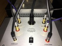
Isn't that an XLR? Can it take the power?
Yes, most certainly.
From Wikipedia:
XLR could accept 14 AWG (1.6 mm or 0.063 in) wire with a current-carrying capacity of 15 amps, suitable for most loudspeakers, but they have been superseded by the Speakon connector for professional loudspeakers.
From Neutrik's catalog:
Dielectric strength 1.5 kV dc
Rated current per contact @ 35°C
3 pole: 16 A
4 pole: 10 A
5, 6 pole: 7.5 A
Rated Voltage < 50 V ac
I've been using XLR plugs and sockets (as power connectors) for all my pre, headamps and power amps, valve and SS for years.
another one done
Here is a shot of 099 on my messy bench. Heat sink temps seem ok. Not sure which pre amp sounds better with the V-fet. First one was the Whammy and now the NuTube. That Whammy really is a sleeper. With both it sounds wonderful. I am going to move the pre amp just had very short interconnects on hand.
Here is a shot of 099 on my messy bench. Heat sink temps seem ok. Not sure which pre amp sounds better with the V-fet. First one was the Whammy and now the NuTube. That Whammy really is a sleeper. With both it sounds wonderful. I am going to move the pre amp just had very short interconnects on hand.
Attachments

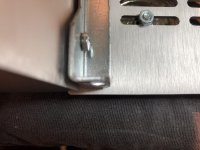
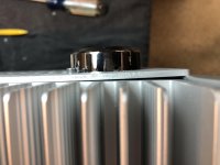
Anyone else having problems getting the screws into the front panel? Everything is loose as can be but the steel bracket is too short for the screw threads to engage with the chamfered hole. I can get the top screw into this side but something isn't square and there is a gap at the bottom while the top is tight.
Attachments
Anyone else having problems getting the screws into the front panel? Everything is loose as can be but the steel bracket is too short for the screw threads to engage with the chamfered hole. I can get the top screw into this side but something isn't square and there is a gap at the bottom while the top is tight.
There was a recommendation a few posts back to use 10mm M4 set screws in the front panel and then to put nuts on them. I found that to be a life saver in that it helped me to square up all the pieces of the chassis.
The front panel just has the logo and led. The rear panel is thinner and has nuts on the other side.
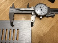
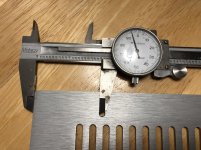
Are these top and bottom pieces really directional? The holes are different on each end and just different enough to be not noticeable by eye.
Are these top and bottom pieces really directional? The holes are different on each end and just different enough to be not noticeable by eye.
Attachments
Anyone else having problems getting the screws into the front panel?
I did manage to get the front panel on, but then I couldn't get all four screws thru the holes in the top plate. I'm going to drill two holes slightly oversize.
Yes, the top & bottom plate only go on one way, at least that's how mine are.
jeff
Alright so it looks like the bottom plate has to rotated 180 and things should line up better 😡 I've had enough for tonight. Might do something more relaxing, like changing a belt on a mid engine Ferrari...
...
Are these top and bottom pieces really directional? The holes are different on each end and just different enough to be not noticeable by eye.
Thanks for pointing that out. That probably saved me some difficulty later.
Would be nice to hear gianluca on this detail…
I never observed directionality on various modushop chassis, so I had luck it seems.
I never observed directionality on various modushop chassis, so I had luck it seems.
Yep, directional if considering a perfectly flush fit, see VFET pt1 thread for details on how to mount the casing without hassle
Hints: directional plates, blank mounting, adjust rear gap first... all in the above mentioned thread
Good luck
Claude
Hints: directional plates, blank mounting, adjust rear gap first... all in the above mentioned thread
Good luck
Claude
Would be nice to hear gianluca on this detail…
I never observed directionality on various modushop chassis, so I had luck it seems.
Who summoned me? 🙂
Regarding your question, you should check the distance between the screw holes and the edge of the cover. If it is 53mm, it should go over the rear panel. If it is 50mm it should be close to the front panel
I'm always saying, Modushop cases are without par, quality vs. Greenies, at least when taking Greenies amount when bought and delivered in Eu
I'm not even bothering (anymore) to think about making Custom case, except in cases that I really need custom case, from various reasons
even if I'm using heatsinks from my shelves, laying low for years so I certainly forgot how much I paid for ( so thinking they're for free), rest of case - front, back , covers - always brings me in vicinity of complete case bought from Modushop
OK, I'm biased, I love Italian ........ food, mcycles, speakers, cars, language ( which I don't know), jeans (wearing enough Casucci pairs from my tender age of 5)
All roads are leading to Rome..... just don't expect of Rome to be 100% perfect ; even Leonardo wasn't perfect ....... but he certainly was more than good enough
- Home
- Amplifiers
- Pass Labs
- DIY Sony VFET pt 2 (N-Channel Build)