Wet sand paper on the floor should be fine.
What happened to fuses and X1/Y1 protection caps that I have in my F5 amp? Trust that Meanwell got it right?
What happened to fuses and X1/Y1 protection caps that I have in my F5 amp? Trust that Meanwell got it right?
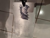
When sanding, layout dye (Dykem) can be your friend. 🙂 It will show you right away where the highs and lows are.
You can get it in a spray which is easier to work with. For those that don't know what I'm talking about, you spray/wipe it on and then when you start to sand the high spots will be removed and the lows will still be blue/red it comes in different colors, blue being the most common.
Remember the glass surface, for flatness if you don't have a stone flat. Also, some wide Sharpies will do in a pinch. There's no real need to do the entire sink, just the T and where it mates, so you can scribble that area with a sharpie if you don't want to get some dye.
JT
where did you measure the temperature? Is it on the heat sink?
48C on V-Fet seems to be too low
What would be the correct V-fet temp?
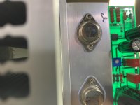
I was using a NC IR device so the number is just a number. What I was looking at was how the heat was sinked into the chassis. The V-fet case was the highest. The t-bar was just below the V-fets and the heatsink was just below that temp. To me that indicated good heat transfer. Maybe I can use something else to get a more calibrated temperature.
48C on V-Fet seems to be too low
What would be the correct V-fet temp?
I was using a NC IR device so the number is just a number. What I was looking at was how the heat was sinked into the chassis. The V-fet case was the highest. The t-bar was just below the V-fets and the heatsink was just below that temp. To me that indicated good heat transfer. Maybe I can use something else to get a more calibrated temperature.
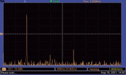
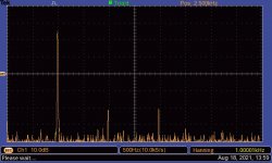
No, that is not second harmonic dominant, but that is at 8W output, which is near maximum power. Check it at 1W (2.83Vrms).
No, that is not second harmonic dominant, but that is at 8W output, which is near maximum power. Check it at 1W (2.83Vrms).
Yes, you are right. Unfortunately my scope is not good enough to show anything meaningful at 1W.
Ben Mah is correct. At 8W output, the VFET amp will show an increased level of 3rd harmonic output. This is as expected (designed). The plots posted actually show a fairly modest level of harmonic distortion, so really nothing to be concerned about.
For reference I got 57°C and 61° C with a glass oven thermometer placed for 30 seconds on top of the Sony V-fet in the P-channel amp. L-bracket measured 47°C, after 1 hour. The amp was on for several hours before measuring.
Starting lapping procedure: CPU & Heatsink Lapping - Are concave, convex, or flat heatsinks best for cooling? - YouTube
Looks so much easier when your surface is just for one little CPU.
Starting lapping procedure: CPU & Heatsink Lapping - Are concave, convex, or flat heatsinks best for cooling? - YouTube
Looks so much easier when your surface is just for one little CPU.
Last edited:
Hey people! I guess this is as good of place as any... I have a bunch of VFETs I would love to have curve traced. The latest, is from a B2 that I bought for parts. As it turns out they all passed the diode and R tests.
So they need to be curve traced, but I don't have the box to do it. It would be awesome, if one of my brothers, or sisters here, could helpme into the lifeboat. This would include several versions and somewhere around 20 devices.
I'm in Rockford, Il. So if you are in driving distance great, or I could send some to you... :O
Any help, or direction would be, most, welcome.
JT
Last edited:
It was easy to lap the T-brackets that the V-fets are attached to, but the large heatsink would grind more on the edges because of the large surface. Still, I think it is worth trying both, because when I place the T-bracket anywhere else the irregularities are immediately more pronounced. I.e. the T-bracket makes a sound like "klick-klock!"
Glad I tried at least. I will comparing the two amps and see which one is the coolest. 😎
Noctua thermal paste is arriving here tomorrow.
Glad I tried at least. I will comparing the two amps and see which one is the coolest. 😎
Noctua thermal paste is arriving here tomorrow.
Attachments
Hi Vunce and Rewind,
Sorry to hear that your heatsink surfaces are not flat where it counts. Good thing you caught that as the heat transfer through a thick layer of paste is not so good. Mine were fine and required no sanding/lapping. I’m surprised that these parts that are supposed to be flat can be that warped. Sanding something made of metal flat by hand is a long slow process. I feel for you guys.
Sorry to hear that your heatsink surfaces are not flat where it counts. Good thing you caught that as the heat transfer through a thick layer of paste is not so good. Mine were fine and required no sanding/lapping. I’m surprised that these parts that are supposed to be flat can be that warped. Sanding something made of metal flat by hand is a long slow process. I feel for you guys.
What size are the screws that hold down the T bracket? My measurements suggest M3x12 but not sure about the thread pitch. Button head screws tend to round out easily so I'm ordering some socket cap style.
One of my heatsinks also seems to have some surface flaws and the bracket doesn't sit flat. Going to get a lesson with the small milling machine at work.
One of my heatsinks also seems to have some surface flaws and the bracket doesn't sit flat. Going to get a lesson with the small milling machine at work.
It has to do whith which tolerances the manufacturer chooses to operate with. I think it is a shame that Modushop sends out heatsinks with scratches and uneven surfaces. They could have impressed 300 future customers, instead many are left with "meh". At least it has a nice front and rear, but all other surfaces have scratches and needle-like shavings sticking out. I managed to place all of the faults inside or under the amp, so I guess that's nice. I won't have to think about it after I am finished with the amp
The heatsinks are extruded and you can't hold tight tolerances. Although I agree if they had time to CNC the screw holes they could have taken a quick skim cut. One heatsink had chamfers around the holes and one did not.
What size are the screws that hold down the T bracket? My measurements suggest M3x12 but not sure about the thread pitch. Button head screws tend to round out easily so I'm ordering some socket cap style.
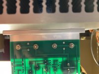
All the Philips pan head screws are M4. The little socket head cap screws are M3. Those are the ones that hold the heat sink brackets for the Vfets, and the top/bottom plates.
It would have been nice to have all socket head cap screws for the chassis.
jeff
Heatsink Update
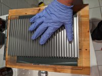
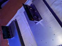
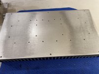
The hump in the center of the heatsink was to high to flatten by hand. I broke out the power tools for this one. A 4” orbital palm sander with dust collection worked great. I started with 100 grit, then 120, 150, 220 and 400. With the vacuum connected to the sander the aluminum dust was removed immediately and kept the surface nice and clean, none of the sanding pads had any aluminum dust build up. I would estimate 0.4-0.5mm aluminum thinkness was removed from the center of this heatsink. The ends of the heatsink were also high, but not as much.
Now the heatsink surface is very flat and the OS T-bar sits flat and makes full surface contact. The other heatsink was not as bad and only needed minor touch-ups. Although this was unexpected extra work, I will sleep better at night knowing the OS has the best possible mounting this design can offer.
(Pics are before and after sanding)
Attachments
- Home
- Amplifiers
- Pass Labs
- DIY Sony VFET pt 2 (N-Channel Build)