
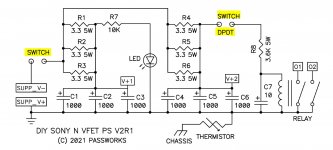
I am a bit confused about 2 switches (or one switch DPDT as noted on the schematic). In the kit I received there is only one switch and it is SPST. Any idea?
that is dual relay switch, for L and R speaker return, most right on sch
power switch (just pads for wires) is on most left
power switch (just pads for wires) is on most left
I don’t have any of this amp yet except the article posted above, but if those switches in question need to open/close at the same time, a single DPDT wired to the PCB pads will work… Not sure what the SPST is intended for. I’m sure there’s a logical reason…
Last edited:
I believe those two switches are indeed the DPDT switch. A single switch that has 2 different contacts. So the single switch device covers the 2 switches seen on the diagram.
As I understand it (kind of) one side of the switch allows connects the power into the amp, and the other side allows the relays to ground the speaker output, to prevent the turn on/off “thump”.
As I understand it (kind of) one side of the switch allows connects the power into the amp, and the other side allows the relays to ground the speaker output, to prevent the turn on/off “thump”.
Last edited:
Haven't opened my kit properly yet, but for the N-channel kit (pt. 2) I agree that you need 1 DPST or DPDT switch (dual pole, on-off is needed).
Let's see this evening what is in my package ...
Regards, Claas
Let's see this evening what is in my package ...
Regards, Claas
PCB Layout does show both connections are to the Power supply connection. Diagram shows wrong -Ve supply on the Switch. If corrected to + V supply, then single switch will do (SPST) ? to connect Power to these two points
PCB Layout does show both connections are to the Power supply connection. Diagram shows wrong -Ve supply on the Switch. If corrected to + V supply, then single switch will do (SPST) ? to connect Power to these two points
I don't think a single SPST switch will work here. Please note that the second switch is after R4|R5|R6.
Yes you are right - then you really do not require DPDT Switch as it gets supplied anyway from switch 1?
Yes you are right - then you really do not require DPDT Switch as it gets supplied anyway from switch 1?
😕
short the DPDT switch part as it gets the Power from Switch 1 through all those resistors.
Since the schematics is showing it as negative input ( which is a typo) and the second part is switch on delay, Pass must have drawn as DPDT.
He should clarify
Since the schematics is showing it as negative input ( which is a typo) and the second part is switch on delay, Pass must have drawn as DPDT.
He should clarify
anyone (who is going to build it!) read article ?
Page 3, bottom :
and there is also clear wiring diagram on Page 5..........and I believe everyone is going to get damn switch in kit

Page 3, bottom :
You will note the more elaborate filtering, made necessary by the VFET's
exposure to rail noise and the larger thump of the circuit on turn-on/off.
It has a DPDT switch for on/off to make this work, and a relay which shorts the
speaker output to ground. R8 at 3.6 Kohm was tested to be adequate to open
these normally closed contacts after a short delay, but if it doesn't you will want
to parallel another resistor with it to make the resistance value a bit smaller.
and there is also clear wiring diagram on Page 5..........and I believe everyone is going to get damn switch in kit
Well, if you don't have a separate switch for the relay ... power for the relay coil will be provided by the 6 x 1000 uF capacitors.
Depending on the time constant / current draw of the output stages, that might not drop the relay quickly enough at switch-off to prevent a power-off thump ...
Depending on the time constant / current draw of the output stages, that might not drop the relay quickly enough at switch-off to prevent a power-off thump ...
anyone (who is going to build it!) read article ?
Page 3, bottom :
and there is also clear wiring diagram on Page 5..........and I believe everyone is going to get damn switch in kit
Yes, I read the article. My only comment was about the switch included in the kit - it is SPST, not DPDT. Probably a mistake...
- Home
- Amplifiers
- Pass Labs
- DIY Sony VFET pt 1