explain how you arranged positions with multiple choices at channel pcbs
have you 9V1 across zeners?
DC offset at output?
reading across 0R47 resistors , up and down?
write specifically for both channels
have you 9V1 across zeners?
DC offset at output?
reading across 0R47 resistors , up and down?
write specifically for both channels
I get 9.1V at zener diodes.
Practically no results by adjusting R27, very small variations around 15mV on one channel and 6mV on the other one, by the way strongly oscillating measure.
750mV and 720mV at amp output.
The same problem on both channels let me think I really made an error, not just bad soldering.
Renato
Practically no results by adjusting R27, very small variations around 15mV on one channel and 6mV on the other one, by the way strongly oscillating measure.
750mV and 720mV at amp output.
The same problem on both channels let me think I really made an error, not just bad soldering.
Renato
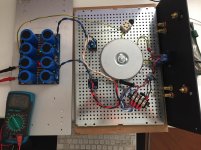
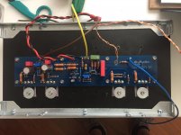
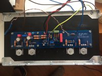
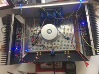
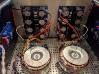
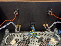
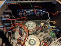
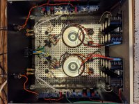
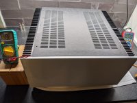
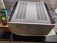
Here the pics.
In the order: PSU test, left channel, right channel, all amp switched on
Thank you
Renato
I can't see R25 resistor mounted. Is it there?
Agreed. Where is R25? It should be next to C2 on the board and it appears empty in your pictures.
Best,
Anand.
Best,
Anand.
I can't see R25 resistor mounted. Is it there?
OMG! I completed tha amp boards a couple of months ago, and I thought I finished.
Thank you, let us see if this the only error 😱
renato
And if you go chasing rabbits...
...you'll find other holes to fall in 😀


These are 4,5mm

And these are M4 screws: on right those that come with the new handles and on the left the ones I used (pssst.. @Gianluca: they didn't fit)

en place


The result 🙂
Big handled big cabinet 😀
...you'll find other holes to fall in 😀
These are 4,5mm
And these are M4 screws: on right those that come with the new handles and on the left the ones I used (pssst.. @Gianluca: they didn't fit)
en place
The result 🙂
Big handled big cabinet 😀
Dear All,
finally I finished my building and just started testing.
The PSU seems correct: light bulb test OK, red and green leds switch on and I measure plus and minus 23V DC at capacitors output with 220 VAC at my main power input (I live in Europe).
I tested both my amp boards and things are not going as indicated by the building guide. First of all, when I switch-on the amp, the light bulb switches on and then quickly switches competely off instead of a lower level light.
The blue leds of the amp corretly swtich on and remain on; but when I measure VDC at input resistor as suggested in the guide to adjust BIAS, I measure 0mV in practice. Things do not change by adjusting R27 resistor (as suggested by the guide I make this test with a clean power wire, no more light bulb).
At AMP output (to be connected to the speakers) I measure 700mV on one channel and 400mV on the other one.
In addition I expected the heatsink to warm up but they remain cold.
Can you suggest me what is going on?
Thank you for the help
renato
Have you tried between input resistor and gnd?
Adding R25 was a success, obviously... you would say! I could adjust bias to both channel. Not sure if this evening I have the time to try to get some music out from the amp 🙂
Thank you for your invaluable help
renato
Thank you for your invaluable help
renato

Uhmmm... My babelfish need an update, doesn't work well! 😀
It says: "Italiani Svegli"? I think no..
It says: "Italiani Svegli"? I think no..
Stupid question:
Do you know if in Pass Labs the meter is connected only to a channel or is there a switch for L and R in order to have bias lectures of both channels?

as far as I know, you'll find similar meter only on PL monoblocks
you can use switch to change reading between channels
use DPDT switch
edit:
or use dual meter, as I have here :
Babelfish (most probably J2) B17 edition – case for future amp – Zen Mod Blog
you can use switch to change reading between channels
use DPDT switch
edit:
or use dual meter, as I have here
:Babelfish (most probably J2) B17 edition – case for future amp – Zen Mod Blog
Good for a Guzzi 😀
Also stereo PLs have a meter:
Pass LabsXA30.8 - Pass Labs
Something like this:
MP0045/3E0NN000 | Interruttore a pulsante Bulgin, A ritenuta DPDT, 3 A Montaggio a pannello | RS Components
Also stereo PLs have a meter:
Pass LabsXA30.8 - Pass Labs
Something like this:
MP0045/3E0NN000 | Interruttore a pulsante Bulgin, A ritenuta DPDT, 3 A Montaggio a pannello | RS Components
Last edited:
or use dual meter, as I have here
Babelfish (most probably J2) B17 edition – case for future amp – Zen Mod Blog
Fabulous "sputafuoco" cabinet! 😎
or use dual meter, as I have here
Babelfish (most probably J2) B17 edition – case for future amp – Zen Mod Blog
Love love love this! Amazing.. well done Zen.. I also have a passion for aviation, this is too cool!
I believe, after all these years of case just layin' on shelf ( powdercoated in a meantime), I finally found proper amp for it - Babelfish XA252
will relocate 0 series pcbs from T-Bed 2 to Flying Furnace ........ I mean - one of these days

will relocate 0 series pcbs from T-Bed 2 to Flying Furnace ........ I mean - one of these days
Noob questions
This doesn't happen to be the noob guidance thread, is it? 😀
I'm looking to make choices on the chassis and input transistors and power supply. I'm currently sporting a pair of DBR62 that with a Sensitivity of 86db @ 2.83v/1m. Should I go with mono blocks? I care more about soundstage, clarity and impact at lower lower listening levels. Will a larger PSU have the capacity to dig deeper if called upon? Do I need a scope to make the best decisions when biasing for dissipation over performance?
... etc.
And another Aleph J is born! Finished it up last night. With the 5U chassis, I'm running about 500mV across R27. One of the MOSFETs is up at around 66C after running for a couple of hours with no signal, but I figure (hope) that should be fine.
I hooked it up to my system, and it sounds fantastic! I wouldn't say it sounds better or worse than my old ARC Ref 110 - just different. Couldn't have asked for a better result.
I also just want to say how fabulous this community is. The resources you all have put together are incredible. It's amazing that someone (me) who has never used a soldering iron before was able to build this amp relying almost entirely on the various posts and information you've put together. So thank you!
Now onto the next project - either a F5 (so I can swap boards out) or a preamp.
P.S. Eric - I assure you that my workbench is nastier than it looks in the previous picture that I posted. Though, I do use cut up Amazon boxes (which are in unlimited supply around here) to protect it from too much paint, etc. getting onto it.
Attachments
-
 PXL_20210725_140033294.jpg512.6 KB · Views: 186
 -
 PXL_20210725_140003793.jpg468.4 KB · Views: 177
 -
 PXL_20210725_135947491.jpg510.4 KB · Views: 175
 -
 PXL_20210725_135931513.jpg543.5 KB · Views: 203
 -
 PXL_20210725_135906422.jpg589.1 KB · Views: 349
 -
 PXL_20210725_012243744.jpg378.8 KB · Views: 339
 -
 PXL_20210725_011013971.jpg383.7 KB · Views: 346
 -
 PXL_20210725_135729632.jpg474 KB · Views: 210
- Home
- Amplifiers
- Pass Labs
- Aleph J illustrated build guide