Here we need to agree on the terms of what we call excitation. I understand by excitation any effect that makes the walls vibrate (regardless of whether the walls vibrates at a resonant frequency or not).It isn't really acoustical excitation but the cabinet being pressurised by the driver in the manner of a bicycle pump with a thumb over the hole.
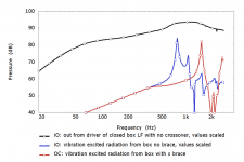
Quite an interesting graph. But, as I understand it, does it not take into account the suspension reaction force ? By the way, the air pressure in the ported box is much higher in vicinity of port tuning frequency and the cone displacement (==>suspention reaction force) is much lower than that compared to the closed box.This plot illustrates the size of the force on the cabinet wall from compressing the trapped air volume and the size of the reaction force on the magnet for the worst case possible of a subwoofer in a small sealed cabinet. It's not quite an apples to apples comparison but it was what I had to hand at the time and it illustrates nicely what is going on in terms of the relative forces. If there is a port or a more typical sized cabinet then the trapped air pressure will reduce substantially. The two terms (distrubuted over the cabinet appropriately) are the forcing terms for a modal analysis of a subwoofer design from a few years back.
Not sure I wholly follow but I am not disupting it. Personally I have never seen the point of doing anything other than simulating the cabinet with drivers since too much relevant physics will be missing otherwise. It is on my todo list to compare the vibrational response of a speaker with that of the cabinet without drivers, the cabinet without holes and a representative panel but I have yet to get round to it.
Here is good point to start study the problem of the acoustical and mechanical excitation of the wall vibration
Comparison of Numerical Simulation Models and Measured Low-Frequency Behavior of a Loudspeaker
AES E-Library >> Comparison of Numerical Simulation Models and Measured Low-Frequency Behavior of a Loudspeaker
Last edited:
Various models demonstrating both in-phase and out-of-phase bracing.
Non tensioned braces can be compared via phase coupling amount and displacement magnitude.
Tensioned braces are not on the same order of magnitude as compared to non tensioned braces in terms of displacement, regardless of phase.
Is this difference arbitrary?
Are the models inaccurate and or a poor representation of the scenario?
Cabinet in Phase vs Tension - YouTube
Here we need to agree on the terms of what we call excitation. I understand by excitation any effect that makes the walls vibrate (regardless of whether the walls vibrates at a resonant frequency or not).
I was picking up on the word acoustical not excitation. When a subwoofer compresses the air in a small sealed volume the ability to identify a small linear motion associated with acoustics/sound, separate motions associated with vorticity and entropy and a steady background state disappears because the fluid motion is too nonlinear. It has to be considered as a single nonlinear motion.
Quite an interesting graph. But, as I understand it, does it not take into account the suspension reaction force ?
Perhaps I am missing something but I cannot see how it would have anything other than a negligible effect on driving the baffle. Whatever forces are present would seem to largely cancel within the driver.
An assembly of cone, suspension, magnet, frame and baffle of course has it’s own dynamics, including resonances within the audible spectrum. With the usual stiff mounting of drivers on the baffle, there is obviously no such thing as canceling within the driver. And hey, we do have a=(2.pi.f)^2.x and F=m.a for starters… 😉
I had very good experience with putting several layers of carpet (with foam back) glued and nailed to the inner sides of loudspeaker walls. After the third or fourth layer even thin wood of 12mm was acoustically dead when being touched with the hand. There was no vibration to be felt any more even with loud music played.
An assembly of cone, suspension, magnet, frame and baffle of course has it’s own dynamics, including resonances within the audible spectrum.
Indeed and they were present in my simulations but they are not driven by forcing from the suspension which was neglected as unimportant when studying the sound radiation from the cabinet. Would be straightforward to include if it wasn't unimportant.
With the usual stiff mounting of drivers on the baffle, there is obviously no such thing as canceling within the driver. And hey, we do have a=(2.pi.f)^2.x and F=m.a for starters… 😉
I await your reasoning with interest about how the forces applied by the suspension on the frame and cone/coil assembly leads to forces on the baffle of sufficient size to exert non-negligible work. A cursory analysis would suggest almost complete cancellation within the driver due to symmetry.
Perhaps I am missing something but I cannot see how it would have anything other than a negligible effect on driving the baffle. Whatever forces are present would seem to largely cancel within the driver.
Equation of a loudspeaker cone motion is
m*a=I*BL - k*x - r*v.
Here we have the magnet system action force I*Bl and two suspention reaction forces k*x and r*v. I think that in the first approximation it would be reasonable to ignore the friction force r*v. So equation of motion is
m*a=I*BL - k*x.
I*Bl and k*x are applied to a speaker magnet system and suspention, respectively. Below a driver resonance frequency I*Bl and k*x are in phase so they compensate each other, above the resonance frequency they are out of phase, so they add up. I am sure that it will not be difficult for you to estimate the magnitude of these forces yourself.
Are the models inaccurate and or a poor representation of the scenario?
Cabinet in Phase vs Tension - YouTube
Interesting movie. What boundary conditions you have applied ?
Equation of a loudspeaker cone motion is
m*a=I*BL - k*x - r*v.
Here we have the magnet system action force I*Bl and two suspention reaction forces k*x and r*v. I think that in the first approximation it would be reasonable to ignore the friction force r*v. So equation of motion is
m*a=I*BL - k*x.
I*Bl and k*x are applied to a speaker magnet system and suspention, respectively. Below a driver resonance frequency I*Bl and k*x are in phase so they compensate each other, above the resonance frequency they are out of phase, so they add up. I am sure that it will not be difficult for you to estimate the magnitude of these forces yourself.
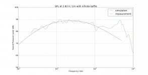
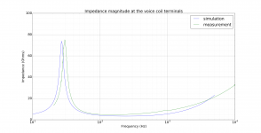
This looks something like the lumped model for the driver which was used to determine the SPL from the cone and the corresponding force on the magnet driving the cabinet vibration. The SPL and impedance is shown below alongside the manufacturer's measurements and looks as one might expect.
Unlike the force on the magnet, the forces from the suspension were not applied to the 3D model of the driver because they largely cancel from symmetry with whatever component remains in the direction normal to the baffle being considered unimportant. It would have been straightforward to include and I likely will at some point in the future with another design if only for confirmation.
Attachments
Interesting movie. What boundary conditions you have applied ?
I need to loop it for longer and add some obnoxious music 😀
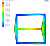
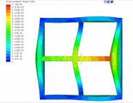
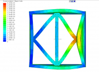
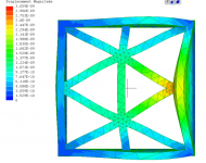
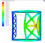
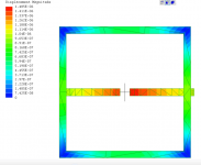
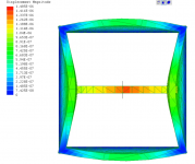
The geometry:
Front +Rear + Sides. No top/bottom. Square 12x12, all sides.
All braces are attached dead center with .75 square cross section (with one exception of small rear truss) .
Conditions:
-The base is fixed
-The input applied is a force directly to a nub on the baffle. Basically the Brace protrudes just past the baffle.
-The entire geometry is a single "dumb" solid.
-All models have the same conditions applied.
-The results are auto-scaled to demonstrate deformation. Meaning one bracing strategy may be displacing 10x more than another but they all scale differently for visualization purposes.
-Material is isotropic.
The good:
They demonstrate the center pole in-phase issue which adds some credibility to how other strategies might behave.
The bad:
Not confident about how to apply constraints. A fixed support is the most usable option, but how to best apply one is not clear.
The tricky:
-How to model a tensioned brace. For a simple single brace, I cut the center out leaving a gap. The gap ends have a an attracting force pulling either side inward. The force is 10x the 'driver input' to the nub.
What to do next, IMO:
-Take the most interesting cases and work towards understanding the actual differences in displacement.
-Devise better fixturing.
-Devise more real world scenarios.
Attachments
-
 T1-simpleBrace.PNG374.5 KB · Views: 152
 -
 T1-simpleCross.PNG551.6 KB · Views: 145
 -
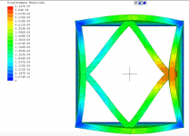 T1-square.PNG729.5 KB · Views: 151
 -
 T1-squreBraced.PNG714.5 KB · Views: 71
 -
 T1-doubleXXbraced.PNG769.6 KB · Views: 67
 -
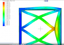 T1-doubleXX.PNG790.3 KB · Views: 73
 -
 T1-truss.PNG800.4 KB · Views: 67
 -
 T1-trussCustom.PNG608.9 KB · Views: 71
 -
 T1-TensionSetup.PNG331.9 KB · Views: 80
 -
 T1-simpleTension.PNG579.7 KB · Views: 69
Last edited:
I only can think of a non-negligible net force when some radiation impedance comes into play. That’s why imho mid frequencies are more problematic (panel resonances appear there too alas). I actually never worry about panels ‘leaking’ low frequency sound. Not from air pressure variations (they are likely to be in order of 1% of the static pressure) in the enclosure, not from the driver frame transmitting vibrations.I await your reasoning with interest about how the forces applied by the suspension on the frame and cone/coil assembly leads to forces on the baffle of sufficient size to exert non-negligible work. A cursory analysis would suggest almost complete cancellation within the driver due to symmetry.
[Edit]forgot there is one exception: radiation impedance rises at resonance frequencies of reflex enclosures, so there you’d expect some net force on the baffle. But still: small panels aren’t going to produce much low frequency sound.
Last edited:
-The input applied is a force directly to a nub on the baffle. Basically the Brace protrudes just past the baffle.
So the force applied is only at one location on the exterior of the box? I don't see how that would approximate either acoustic energy applied in all directions inside the box, or vibrations traveling along/through the walls all around the box. The in-phase movement of the right and left walls seems to me to be a result of this choice in applied force which is not anything like the forces of concern we discuss in enclosure design.
In future plots can you turn off the autoscale and define one that is the same for all models?
@augerpro
What you just described is similar to my thought process. There's pressure, and there's the resonance modes other than those created from wall pressure.
As these conversations have evolved, the mechanical force induced by the driver came up too. So now I'm understanding three modes acting on the cab.
Criticism about using a simple brace, coupling parallel walls, was an initial talking point. The problem alleges that coupled/simply braced parallel walls tend to move in-phase which is apparently bad (I have no personal take, because, noob).
So what force will induce the in-phase motion of the cab? To my mind, pressure is ruled out because the force should act uniformly on the internal surfaces; I've not seen any claims for this in the thread so let's assume pressure is not at play.
That leaves the modes/resonance (the complicated stuff). My naïve sense for a resonating cab is that the entire surface is excited and oscillating as a whole. It would not occur to me that a coupling a brace as mentioned would cause this in-phasing. As the driver reaction topic arose I started looking at the forces induced via driver; this from hifijims depictions of in-phase movement.
This brought the current sims about; how to replicate the in-phase problem using the driver forces acting on the front baffle. If this is an incorrect assumption, I'm not sure how to go about creating the in-phase scenario. If treating the entire cab as a resonating body (instead of from driver input), I don't quite understand how the simple brace is such a player in the overall behavior. The aspect ratio alone should imply that a rod style parallel connection will be flapping and buckling like crazy as the off-axis force causes deflection. It seems like a braced single pole gyrating would be a bigger problem then a tendency for the panels to act in unison.
My suggestion is that placing the simple brace under tension can alleviate any compression buckling, and stifle a tendency for walls to move in-phase. That was said to be erroneous, so I'm trying to baby step through the situation.
Do you have a suggestion for how to replicate the in-phasing using a different set of forces?
As far as constraining the scaling, I'm working on that now, but I need to whittle down the number of models. So far I find the mini-truss version to be interesting as it has the most isolating effect on the reaction at the rear vs front baffle. The simple brace and the simple brace under tension are the two obligatory items to look at.
The dynamics involved may be out of my scope of capability. However, I can't see how the geometry of the static structure can be ruled out and that's where the sims are at right now. I can look at pressure and stiffening for that, which is static, but that was not a criticism that I can reconcile with the phase phenomena.
Other than getting the displacement comparisons developed, is there any other controls you'd put in place/loosen?
Do you have a suggestion for how to replicate the in-phasing using a different set of forces?
I don't. Andy should be able to shed light on that.
...So what force will induce the in-phase motion of the cab? To my mind, pressure is ruled out because the force should act uniformly on the internal surfaces; I've not seen any claims for this in the thread so let's assume pressure is not at play. ...
I will offer some informed speculation... It would take finite element modelling of a particular cabinet to define the mode shapes (deflected shape), and every cabinet is different. But I can offer some educated speculation...
One possibility is a high-aspect ratio baffle with a driver mounted asymmetrically. An example would be a tall, narrow baffle with a woofer mounted at the bottom. The forcing function is applied much closer to the bottom than the middle. This could (speculation) impart a moment on the top and bottom such that those two panels are driven in phase. When the driving frequency matches the top and bottom panel resonance, they will resonate "in phase". I tried to illustrate this in post #29.
Another possibility is a smaller panel with a first mode resonance which happens to be at the same frequency as a larger panel's second mode frequency. So how would this work?
Each panel of an unbraced cabinet will have a natural resonance if it were simply supported... it is not simply supported, nor is it clamped (as assumed in the paper). Each panel has an end-moment fixity provided by the adjacent panels. But for talking purposes let’s assume simply supported.
Let's say the baffle has a first mode resonance at 100 Hz. In this mode the panel's deflection shape in 2D is a simple arc. Sometimes it is modelled as an ellipse, or a parabola. In 3D it might look like a section of a sphere.
Let's say the baffle has a second mode resonance at 190 Hz, and this mode shape is "S" shaped. The top half of the baffle is deflected out of phase with the bottom half. The center of the panel is not deflected. This scenario does not require that the driver be mounted asymmetrically. Now let's further assume that the top and bottom panels have a natural first mode resonance that is close to 190 Hz. In this case, the baffles second mode resonance will drive the top and bottom panels into resonance, and they will be moving “in phase”.
As I said, this is theoretical speculation, and every cabinet is different. But these are two plausible scenarios where two panes could be driven to resonance in a way which is "in phase".
I do hope that Andy has not been discouraged from adding to this discussion. Several times in the past he and I have been on opposite sides of an argument, and it is pleasant to find myself in agreement with him.
j.
A lot of great info, @hifijim.
The specific requirements of mode geometry needed to have the in-phase effect would be cause to rule out a pressure that will act uniformly against the walls. Considering that a single force applied via the frame does produce the effect, that seemed like a direction to pursue.
But if the pressure is oscillating the walls, maybe pumping them like a swing set, then it makes sense that the walls finally reach whatever natural mode and overtake any effect from pressure uniformly pushing/pulling. As you point out, there are numerous factors at play and a simple change in panel dimensions can play a role.
I've given an extremely wide berth to allow for conserving the single brace as a functional strategy. Carte blanche; dimensionless freedom regarding material, placement suggestions, geometry etc. That one possible scenario where the panels move in phase is the reasoning behind why a single brace is bad practice, well, that's a pretty significant statement. Significant, as in a basic tool being banned from one's toolbox of bracing strategies. It's literally the simplest, most direct, most minimal brace I can think of. Almost analogous to the first mode of bracing. So the toolbox is now short a straight slot screwdriver. I want my screwdriver back and it's been equipped with the finest Korinthian leather grip and a force vector jet pack. But in phase panels are really gonna be the death knell?
It would seem that some very definitive proof is in order, and well worth taking the non-physicist all the way through the entire word problem. The math, the FEM, the mechanical properties of the materials, the cab dimensions, everything, from zero. And if in the end there is not some trivial tweak one can make like adding a damping layer, repositioning the brace, re-tensioning brace, and so on; well, fair enough, 86 the screwdriver.
Here are some results from my construction methods thread (easiest to read from my website) comparing no bracing to very simple bracing with the brace at the center of the panel (side to side, and front to back). The mic was positioned at this center point and 1/2" away from the panel. One measurement at the rear panel, and one at the side:
.


.
Last edited:
Very cool-
I'm interested in your value judgment as to the specific tests.
I've heard explanations that promote pushing the frequency higher. Higher and flatter is presumably most desirable.
Great examples; just barebones simplicity. There must be dozens of ways to manipulate/deviate away from the basic setup to various effects and still utilize a minimal approach.
As to panels in phase or not, are the measurements indicating this action or will other bracing geometries behave the same?
Also, what's the CLD construction consist of?
Last edited:
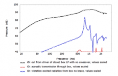
Well, it is disputed, but the LS50 white paper gives some clues. Bracing highens resonance frequencies and sometimes because of that they become more audible, where nothing happens in the amplitude domain. Bear in mind that cabinet walls also act as radiators with their own radiation impedance. Bracing lessens the excursion of the panel, but the smaller excursion at a higher frequency leads to about the same sound power output.

The other interesting graph from the paper I think is that in which sound production from the cabinet due to air pressure variations is compared with the sound production caused by vibrations of the drive unit. All FEM/BEM analysis and a bit of marketing is involved, but all the same from some of the pioneers in the industry...

The other interesting graph from the paper I think is that in which sound production from the cabinet due to air pressure variations is compared with the sound production caused by vibrations of the drive unit. All FEM/BEM analysis and a bit of marketing is involved, but all the same from some of the pioneers in the industry...
Attachments
- Home
- Loudspeakers
- Multi-Way
- An interesting paper on bracing lightweight cabinets