Placing a heavy mass on a panel does not make it non resonant, it just takes more energy to get the increased mass moving. The rigidity must be increased to move the frequency up. As there is less energy in higher frequencies it is less likely to be excited during normal music. Sure, if you play a loud tone at that frequency you could get it moving but in reality does this occur?
Placing a heavy mass on a panel does not make it non resonant, it just takes more energy to get the increased mass moving. The rigidity must be increased to move the frequency up.
At a resonance the mechanical energy in the system is being harmonically exchanged between the kinetic energy of the motion and the energy stored in bending the panel. For the same bow shape of the lowest mode the energy stored in bending the panel will not change significantly with the addition of the mass therefore the panel will have to move more slowly to reduce the kinetic energy to match that of bending the panel. The frequency of the resonance reduces.
As there is less energy in higher frequencies it is less likely to be excited during normal music. Sure, if you play a loud tone at that frequency you could get it moving but in reality does this occur?
At high frequencies it takes much less displaced volume to make an equally loud noise (e.g. the area and displacement of equally loud woofers and tweeters) plus moving faster at high frequencies requires more energy. I would suggest it is not a useful way to look at things.
What is driving the vibration of the cabinet is the reaction to the movement of the woofer and tweeter (and the internal air pressure at low frequencies). So if the woofer and tweeter are playing equally loudly then whatever it takes to do this in terms of forces is around to drive the cabinet similarly. The "strength" in terms of radiated sound levels is pretty much the same. What is different though is the relative sizes of various quantities leading to different responses.
At high frequencies the number of modes per octave increases greatly leading to a single tone driving lots of modes rather than none. This tends to be an averaging effect leading to a fairly even response without the large peaks and dips seen at low frequencies where there are few modes per octave. It is at low frequencies not high where a single tone may drive a cabinet strongly or weakly depending on where the frequency lies with respect to the resonances.
And then again it is likely room effects will rule, not cabinet resonances at relatively low frequencies. Even at mid frequencies extensive attention to cabinet transmission loss seems not that useful to me. Better get that cavity damping right.
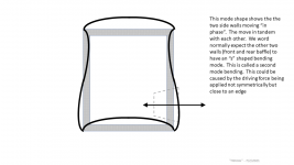
Btw, did I understand it right that not everyone grasped the concept of two cabinet walls moving in phase? We need more pictures here!
Btw, did I understand it right that not everyone grasped the concept of two cabinet walls moving in phase? We need more pictures here!
And then again it is likely room effects will rule, not cabinet resonances at relatively low frequencies.
Indeed. Nonetheless if folk have an interest in quality then ensuring their cabinet is inaudible at low frequencies is still a worthwhile objective even though it is relatively straightforward and failing to achieve it will only degrade the overall performance of the speaker a small amount.
Even at mid frequencies extensive attention to cabinet transmission loss seems not that useful to me.
Transmission loss refers to how sound is reduced by a barrier like a wall between two rooms. This is misleading because it is not what makes a good speaker cabinet. The internal air pressure driving the speaker walls is only significant at low frequencies and is relatively unimportant in a good design. What primarily determines a good performance is reducing the amount of energy transferred from the vibrating drivers into the cabinet and then how much of the energy that is transferred can be absorbed by effective damping materials rather than radiated away as sound. The frequency distribution of the resonances is also relevant because midrange resonances are audbily more intrusive than low frequency ones of the same level.
Better get that cavity damping right.
This is a cheap and straightforward task if one understands how stuffing absorbs sound. Unfortunately many DIYers have taken to sticking thin layers of felt on the inside of walls where it is the least effective. Indeed in another thread someone was proposing to "improve" a commercial speaker by replacing the folded piece of wadding in the middle with felt stuck to the walls.
Btw, did I understand it right that not everyone grasped the concept of two cabinet walls moving in phase? We need more pictures here!
I suspect it rather depends on what people want from the hobby. Is there more fun in cracking on with building lots of speakers with only a vague and wonky understanding of what is going on and then discovering the performance after construction or to invest more time studying and analysing on paper in order to get closer to getting it right first time, build fewer speakers and then checking rather then discovering the performance?
Btw, did I understand it right that not everyone grasped the concept of two cabinet walls moving in phase? We need more pictures here!
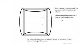
It seems to me moving in phase is not the same as moving in the same direction in anything but a one dimensional object. So while two side walls may be in phase, the peaks and troughs of the waveform are pointing in opposite directions. A brace tying the two panels together helps tremendously. Sure there might be a certain construction that allowed a brace connecting two panels moving in the same direction to create a new lower resonance, that is hardly the norm.
Now if you want to make the case that is the norm at higher frequencies, well ok, but that is not what was going on with the OP's cited paper.
Last edited:
I suspect it rather depends on what people want from the hobby. Is there more fun in cracking on with building lots of speakers with only a vague and wonky understanding of what is going on and then discovering the performance after construction or to invest more time studying and analysing on paper in order to get closer to getting it right first time, build fewer speakers and then checking rather then discovering the performance?
Loudspeaker design has progressed more through experiment than any theoretical know-it-all has ever accomplished. Maybe that can change now with modern computer modeling, but that's just getting traction now with big manufacturers.
I can test the mounting with those rubber grommets for bolts, Is there any other specific features you know work that I can test? Simply needs to work in 18"x8.5"x10" box that would be used as a typical 2-way standmount speaker.
Andy, you were quite right about that transmission loss. Forgot to mention that. You'd wish everyone had read the old stuff from Wireless World (seventies that is).
Btw, did I understand it right that not everyone grasped the concept of two cabinet walls moving in phase? We need more pictures here!
I threw something together which hopefully clarifies this concept.
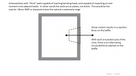
This is a simplified 2D diagram (what we aerospace structures engineers used to call a cartoon) showing how the structure deflects in response to a force. I real life, the box is 3D and has a top and bottom which stiffen the structure but which also have their own deflections.
Jim
Attachments

??? All the driver is doing is pressurizing the air mass in the cab, so all six sides expand on compression [driver in] and suck in on rarefaction [driver out], assuming it's sufficiently flexible of course. 😉
This is what bracing is for, to keep it from 'breathing'.
This is what bracing is for, to keep it from 'breathing'.
My 2D diagram applies to the situation in the paper. I was illustrating what it means when opposite cabinet walls vibrate out of phase (in opposition) or in phase (in tandem).
The majority of the energy transmitted to the cabinet structure comes from the driver motor, transmitted through the basket, directly into the baffle. A much smaller level of energy is transmitted through the air in the cabinet and into the walls as acoustic loading.
The forces and deflections I am describing are inconsequentially small until the driving frequency hits that first mode resonance.
I have heard that a powerful subwoofer driver in a weak unbraced cabinet can cause that cabinet to “pant”, or bulge as you describe… all 6 walls puffing in and out in unison. But I have never seen it. My understanding is that when this defect is present, it happens over a broad band of frequencies. This behavior does not sound like a resonance. It sounds to me like simple elastic flexing of the structure due to the internal pressure.
OK, but none apply to speaker cabs other than parallel walls are in phase in both compression, rarefaction.
The motor vibrations are minor, so the pioneers originally mounted them with no gaskets and the formed rim bit into the wood to seal, damp it, though used eight mounting points on larger drivers.
Of course they didn't have high Xmax, but gasket technology being what it is nowadays, seems like advanced versions of Altec's, etc., rubber/cork composites + motor brace should suffice.
Regardless of the driver though, I always recommend tying the driver to the cab [mass load] to ensure a stable working platform and ideally done with a motor/frame clamp with no baffle mounting hardware, just a high quality closed cell neoprene gasket to seal it.
One early manufacturer mounted the driver to a skeleton frame and just dropped the cab down over it [~aperiodically damped].
Right, the lower the fundamental, the wider the [harmonic] BW, so the goal is to push cab's resonance either above or below it.
Yes, in the extreme it does make it sound elongated as it's modulating the driver out of sync with the higher frequency systems. Under hung motors driven out of the gap sounds the same IME.
Loudspeaker design has progressed more through experiment than any theoretical know-it-all has ever accomplished. Maybe that can change now with modern computer modeling, but that's just getting traction now with big manufacturers.
This looks rather like a statement of faith. The reality is that loudspeakers from established commercial manufacturers have been designed primarily on scientific/engineering principles rather than blindly using measurements since the 40-50s when a number of acoustics text books were first published. These text books contain various worked examples for loudspeakers, drivers, microphones and similar and have formed the basis for design methods for those tasked with designing loudspeakers for 75 years or so. The Thiele-Small design equations are an example of this which most DIYers are aware of. On the mechanical side things are even better developed due to the much wider areas of application. Linear FEM reached maturity at the end of the 60s whereas acoustic BEM reached maturity about ten years later. Of course these were initially used only in high tech engineering industries rather than low tech ones like speakers but as computer costs have reduced they have been adopted more and more by medium and low tech industries.
Computer modelling is only the latest evolutionary step in applying scientific knowledge to designing loudspeakers. Earlier ones were a calculator, a slide rule and sums in a notebook with a pencil. I am old enough to have started engineering with a slide rule and sums in a notebook. The quality of engineering today has been improved greatly by the huge increase in the efficiency of applying scientific principles to design.
Experiments obviously have a role in engineering development (would you trust something that hadn't been checked by measurement?) but that role is primarily as confirmation of the reasoning being used to design and develop rather than as a tool to gain insights. Measurements are pretty poor at this as can be seen on this forum and indeed in this thread. People tend to know a bit about what happens from things like meausrements but without the relevant scientific/engineering knowledge they don't know how and why and so can't apply it reliably to design loudspeakers.
I can test the mounting with those rubber grommets for bolts, Is there any other specific features you know work that I can test? Simply needs to work in 18"x8.5"x10" box that would be used as a typical 2-way standmount speaker.
Well the engineering/science would indicate that soft mounts for tweeters is generally a good idea, woofers generally a bad idea and midranges debatable with one or two things that can be done to shift towards good. Can you use your measurements to confirm this?
The majority of the energy transmitted to the cabinet structure comes from the driver motor, transmitted through the basket, directly into the baffle. A much smaller level of energy is transmitted through the air in the cabinet and into the walls as acoustic loading.
The forces and deflections I am describing are inconsequentially small until the driving frequency hits that first mode resonance.
This isn't quite right. At low frequencies for a subwoofer in a small cabinet the forces on the cabinet from the air inside are much larger than those from the driver. Competent bracing will minimise the movement of the cabinet walls although it is unlikely any of it is particularly audbile because of the insensitivity of the ear at these frequencies, the large wavelengths and because the cabinet isn't resonating but largely following the varying air pressure.
At higher frequencies with much larger cabinet volumes with respect to the volume displaced by the driver the situation swaps and the forces from the internal air pressure become negligibly small. It is also at these higher frequencies that the lowest frequency cabinet resonances start to appear which raise the displacement of the cabinet to much higher levels than the stiffness alone would do. This is where one needs to apply engineering knowledge in order to reduce the cabinet movement in order to achieve hopefully inaudbile levels of sound radiation.
This isn't quite right. At low frequencies for a subwoofer in a small cabinet the forces on the cabinet from the air inside are much larger than those from the driver....
In physics, the statement “much larger” usually means that one of the compared quantities is an order of magnitude larger. If we are talking about the contribution of mechanic and acoustic excitation of mechanical box vibrations, the statement "acoustical excitation is much larger than mechanical one" is valid only for very small ported boxes near the port tuning frequency. Otherwise, the contributions of both excitation mechanisms will be quite comparable.
The second point is that mechanical structural modes typically correspond to the simply supported boundary condition (no torque on the edge, so the edge can rotate), thus lowest structural modes can't be exited acoustically, only mechanical excitation is possible.
Last edited:
Well the engineering/science would indicate that soft mounts for tweeters is generally a good idea, woofers generally a bad idea and midranges debatable with one or two things that can be done to shift towards good. Can you use your measurements to confirm this?
I can try. I use a 2" Peerless with wide bandwidth for these tests, and I think the midrange application is where my focus is. What mounting method can you suggest?
At higher frequencies with much larger cabinet volumes with respect to the volume displaced by the driver the situation swaps and the forces from the internal air pressure become negligibly small. It is also at these higher frequencies that the lowest frequency cabinet resonances start to appear which raise the displacement of the cabinet to much higher levels than the stiffness alone would do. This is where one needs to apply engineering knowledge in order to reduce the cabinet movement in order to achieve hopefully inaudbile levels of sound radiation.
What are the mechanisms at work here and what method would suggest to suppress them?
In physics, the statement “much larger” usually means that one of the compared quantities is an order of magnitude larger. If we are talking about the contribution of mechanic and acoustic excitation of mechanical box vibrations, the statement "acoustical excitation is much larger than mechanical one" is valid only for very small ported boxes near the port tuning frequency. Otherwise, the contributions of both excitation mechanisms will be quite comparable.
It isn't really acoustical excitation but the cabinet being pressurised by the driver in the manner of a bicycle pump with a thumb over the hole. This plot illustrates the size of the force on the cabinet wall from compressing the trapped air volume and the size of the reaction force on the magnet for the worst case possible of a subwoofer in a small sealed cabinet. It's not quite an apples to apples comparison but it was what I had to hand at the time and it illustrates nicely what is going on in terms of the relative forces. If there is a port or a more typical sized cabinet then the trapped air pressure will reduce substantially. The two terms (distrubuted over the cabinet appropriately) are the forcing terms for a modal analysis of a subwoofer design from a few years back.
The second point is that mechanical structural modes typically correspond to the simply supported boundary condition (no torque on the edge, so the edge can rotate), thus lowest structural modes can't be exited acoustically, only mechanical excitation is possible.
Not sure I wholly follow but I am not disupting it. Personally I have never seen the point of doing anything other than simulating the cabinet with drivers since too much relevant physics will be missing otherwise. It is on my todo list to compare the vibrational response of a speaker with that of the cabinet without drivers, the cabinet without holes and a representative panel but I have yet to get round to it.
Regarding "in phase panels"
Questions:
If strategy A panels move "out of phase" at displacement distance X
and
strategy B panels move "in phase" at displacement distance x/4
what is the preferred strategy?
If strategy B panels move x/10, is this an arbitrary dimension based on the phase relationship of the panels-- in that they are "in phase", hence bad under any displacement magnitude?
I can try. I use a 2" Peerless with wide bandwidth for these tests, and I think the midrange application is where my focus is. What mounting method can you suggest?
What are the mechanisms at work here and what method would suggest to suppress them?
Not sure how representative the forcing from a small light 2" driver will be compared to the forcing from a big heavy woofer but some of the physics will be present. Soft grommets seemed to be the commonest thing mentioned but I suspect it may be wise to also consider some form of guide to keep the motion close to normal to the baffle. It has been discussed before and so there is likely to be more reliable advice than mine out there. I did not mention any theory in order not to get in the way of the measurements.
Additional questions part I:
If driver reaction is the key mode to induce problematic "parallel resonance" (rather than pressure)---- what is the input force? In terms of modeling the phenomenon, is a force applied to the driver basket (and into the baffle) along the cone excursion axis? What is a typical input force, in terms of measurement, induced into the baffle via basket/frame of the driver?
Original questions still in need of response:
Regarding "in phase panels"
Questions:
If strategy A panels move "out of phase" at displacement distance X
and
strategy B panels move "in phase" at displacement distance x/4
what is the preferred strategy?
If strategy B panels move x/10, is this an arbitrary dimension based on the phase relationship of the panels-- in that they are "in phase", hence bad under any displacement magnitude?
- Home
- Loudspeakers
- Multi-Way
- An interesting paper on bracing lightweight cabinets