@markbakk
I read through the KEF paper and there's a lot of material there. Looking at the driver transmission into the cabinet, it would seem to be a non issue. I suppose those sims in my post on driver force induced wall displacement are somewhat indicative of that behavior, but nothing to really focus on.
The X brace (or whatever they call it) has a lot of clues when comparing measurements. First off, it contacts all six sides, geometrically at least, and crosses the entire span of each wall. This is sort of another minimalist approach in that the least amount of bracing is employed to contact every side and span the entire length. The results of braced version vs unbraced are very similar in behavior to augerpro's example of the simple cross-brace.
Where things get crazy with the KEF is once they put the CLD between the brace. But, IMO, this would act less like a brace and more like a shock absorber coupled forcefully to the walls. Plus there is the claim of standing wave management, due to compartmentalization. In terms of the performance of the full length rigid X vs the pair of sticks, they both look like cowbell. Just that the X has more cowbell. I think a lot more cowbell can yet be squeezed from the minimal brace based on the KEF/augerpro measurements.
What the KEF has going for it is standing wave management, large brace to surface contact using minimal geometry, and the big player that is the constricted CLD layer.
What the KEF appears to have working against it is the fact the the front baffle is not a structural element. That simple issue kinda shoots holes in how rigid the enclosure really is. The heavy bracing is probably needed to compensate for an open ended enclosure and again, its not even a rigid brace anyway due to the CLD. Or maybe it is? Viscoelastics are said to increase in rigidity with an increase in input, but they make no mention of what's really going on at the interface.
A notable detail on augerpro's side vs rear measurements is that the sides see more attenuation. Maybe this is to do with that fact the the sides have a shorter span, hence easier to attenuate. I've seen mentions that this is preferable in terms of proximity in the room.
@augerpro, I checked out your full writeup at the site, so my earlier questions were answered there. Good stuff!
Attachments

Last edited:
Earl Geddes also uses a damper in his bracing, I guess we all know that here.
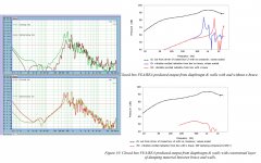
KEF uses a prestressed mounting of the driver on the baffle: the magnet is pushed into pieces of the damping compound while the unit is mounted on the front. More elaborate techniques such as magnet mounting (like the 104.2) were either too expensive or didn't pay off enough. But the baffle is braced this way.
CLD techniques can bring very much, especially with thin wall enclosures. Less so with relatively thick MDF in a small enclosure. The applied bracing with the damper element will bring an end to the primary resonance of the panels, it might also bring down a second order resonance by damping the rotational movement at the junction instead of just shifting it up higher in frequency.
Actually the sides of my box are wider. But to me it makes sense they should see a bigger impact from bracing since the unsupported span is longer before a brace is attached. Another thing I like about the side measurement is that the panels are identical, which isn't true of the rear panel since the front panel has a hole and driver attached. But I've just taken both measurements not knowing which I should really rely on.
Another note about my CLD braces. These are two piece braces glued together with whatever was indicated in the test. So the constrained layer is under shear motion which is what Geddes and others had advised. It is interesting that Kef went with a constrained layer that is under compression. I may have to try that. I don't think the liquid adhesives would work well, but the 3M VHB tape might be the ticket. I did test it with the above method and it was basically identical to the Weicon Flex 310M, but in compression CLD I think the two would be quite different. More a pain to construct though.
Another note about my CLD braces. These are two piece braces glued together with whatever was indicated in the test. So the constrained layer is under shear motion which is what Geddes and others had advised. It is interesting that Kef went with a constrained layer that is under compression. I may have to try that. I don't think the liquid adhesives would work well, but the 3M VHB tape might be the ticket. I did test it with the above method and it was basically identical to the Weicon Flex 310M, but in compression CLD I think the two would be quite different. More a pain to construct though.
One thing I'd like to get around to trying is incorporating a 1/2"x4"x4" rubber "puck" as a central axis point for the bracing. They sell on Amazon for not too much coin. Attaching the braces to it shouldn't be a big deal using a hole/steel sleeve through which a screw can hold the brace.
https://www.amazon.com/s?k=1/2"+rubber&ref=nb_sb_noss_2
https://www.amazon.com/s?k=1/2"+rubber&ref=nb_sb_noss_2
Last edited:
Posts 58-64 are getting nicely honed in on minimal brace iterations.
Markbakk, you are right over the target so far as what this means for the application of lightweight construction, IMO. Not a requirement, but the brace via magnet has a certain allure if it can be made to work and it's something I'm looking at, using a Purifi PTT6 driver. I'm too fearful to mechanically fix it, full force through the rear of the driver, especially via the magnet. But it does seem plausible to do an elastic CLD interfacing the rear driver to a large diameter strut, being both transmissible as well as cutting the panel span in half. A bit of an odd configuration but it would be fun to try.
And to augerpro's mention of applying a shear vs compressing the CLD; to my mind shear would give you a greater range of options and allow you to maintain the relative simplicity. The example I'm thinking of would be to switch to concentric tubes that will allow you to have all the surface in the world. And you can nest numerous instances of the CLD. For example a two layer tubular CLD, consisting of three tubes with the CLD inbetween. Plus if you put the largest diameter tube centered between the panels that will boost your strut stiffness significantly, perhaps helping the long brace span.
Puppet adds the icing on the cake with the mention of using an additional interface, the puck as the example. This is why the simple braces are so interesting; the more you can channel the energy into fewer structures the more options for management arise. It would be great to somehow channel all unwanted energy into a single point and soak it up from there, where things like weight adjustments, springs, rubber pucks, etc. can open up more options. It's beyond me if these tricks are viable in the scope of a cabinet, so maybe I'm getting out into left field.
H60s use a tunable spring called a vibe-absorber. There's not much info about them online, but I used to install them and know the geometry and materials used. It's just a steel plate with smaller bolted plates that allow for tuneability. The "springs" are actually titanium legs with a tapered profile. Not saying this would work but it would sure be cool if it did! But more generally, it would follow that the fewer bracing members involved, the more options you have to make them do work.
Check out the vibe-absorber in action-
H-60 CABIN VIBRATION ABSORBER - YouTube
Attachments
Last edited: