Yes, 2.5 sq.mm is more than enough. By the way, your lawn is nice! 🙂
Haha, yes, i have quite a big yard for modern standards, and it was freshly mowed 😀
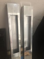
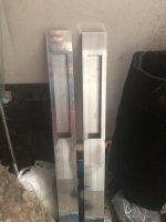

So are you going to paint these?
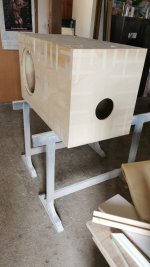
No, i polished it, and i think it will be a nice contrast to black cabinets/speakers.
No, i polished it, and i think it will be a nice contrast to black cabinets/speakers.
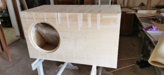
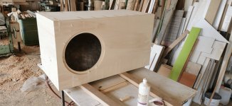
Well, then you may start adding the damping, wire the crossover and test if everything (including crossover) is OK. Looking forward for photos of the LF cabinet.
Last edited:
Well, then you may start adding the damping, wire the crossover and test if everything (including crossover) is OK. Looking forward for photos of the LF cabinet.
I did crossover today but i didnt solder it, will do tomorrow.
Attachments
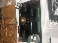
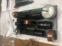

Oh, that looks beautiful, but make sure to use enough flux and solder to ensure reliable connections. And once the boards are finalised, you may also apply a coat of "clear" over the solder-side to prevent any long-term corrosion to the electrical contacts.
Solder isn't supposed to take the place of good mechanical gas-tight joints. Laying the wires side by side and soldering them might be fine if you expect to disassemble them anytime soon. On the other hand changing ones mind would not be unusual for a crossover. 😉
Solder isn't supposed to take the place of good mechanical gas-tight joints. Laying the wires side by side and soldering them might be fine if you expect to disassemble them anytime soon. On the other hand changing ones mind would not be unusual for a crossover. 😉
Well, in hindsight, should have place non-coils components closer so i can do lead - to - lead, but hey, its not bad. I have some good solder tin, so im hoping it will hold 🙂 Did well when i was soldering new pot to the amp. For wire i used solid wires, im thinking they are 1.5mm so good enough. They are much firmer and easier to hold in place while i solder them 🙂
Only thing im not happy is the connector positions, but could be worse i guess 😀
Oh, that looks beautiful, but make sure to use enough flux and solder to ensure reliable connections. And once the boards are finalised, you may also apply a coat of "clear" over the solder-side to prevent any long-term corrosion to the electrical contacts.
Thanks Virus 🙂 Good idea for clear coat, il look for it.
I didnt have time today to solder it and test it, so it will have to wait for next week.
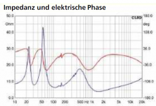
Regarding check if crossover is ok, what impedance value should i see on input connectors (amp) with speakers connected to the crossover ? *See the attached pic for speaker impedance response, i used 99.9% same components so it should be preety much the same.
Attachments
Cold solder joints are more critical with a side by side joint so make sure they shine.
I like working with solid wires. After a long time in a vibrational environment, unless they are supported they may break due to metal fatigue.
I like working with solid wires. After a long time in a vibrational environment, unless they are supported they may break due to metal fatigue.
Assuming you have the means to measure impedance (vs freq), you need to see at least the rated speaker impedance (minimum), which appears to be 4 ohms in your case (from picture in #190). A little to this side or that may still be alright.
Alternatively, if you don't want all the electrical mess, the easy way is to connect the completed network to the amplifier and make sure that there is only bass on the LF and only treble on the HF. And be careful not to feed the bass channel into the HF by mistake, and start at low power.
Alternatively, if you don't want all the electrical mess, the easy way is to connect the completed network to the amplifier and make sure that there is only bass on the LF and only treble on the HF. And be careful not to feed the bass channel into the HF by mistake, and start at low power.
Last edited:
Cold solder joints are more critical with a side by side joint so make sure they shine.
I like working with solid wires. After a long time in a vibrational environment, unless they are supported they may break due to metal fatigue.
Got it, tho crossover will be outside of speakers, near the amp, as a standalone tech showpiece 🙂
Assuming you have the means to measure impedance (vs freq), you need to see at least the rated speaker impedance (minimum), which appears to be 4 ohms in your case (from picture in #190). A little to this side or that may still be alright.
Alternatively, if you don't want all the electrical mess, the easy way is to connect the completed network to the amplifier and make sure that there is only bass on the LF and only treble on the HF. And be careful not to feed the bass channel into the HF by mistake, and start at low power.
Well, i only have multimer tool, i dont have oscilloscope.
I will do test slowly, tho my "tweeters" are infact fullrange speakers, so i think they wont die immediatly from LF signal 😛
FRS 5 X - 8 Ohm | Visaton
Well, then no worries about blowing them, but do remember that the network is supposed to let only the treble reach your full-range "tweeters". 😎
Best is mechanical, such as using modern roofing nails in lieu of the pioneer's nail + cardboard squares: roofing nails - Google Search
Otherwise I prefer carpet double stick tape: carpet double stick tape - Google Search
Otherwise I prefer carpet double stick tape: carpet double stick tape - Google Search

Well, it's nice to know that you're happy with the sound of the array. Though the 8-9 ohm reading would be at some preset frequency used by the multi-meter (not very useful), you would mostly know (by ear) if something is seriously wrong. If you feel it is working, then it probably works. You could feed the woofers as well, along with the arrays, after which you would (roughly) know if you have sufficient amplifier power for the room under consideration.
Besides, good to know that your floor is carpeted (picture above). Carpets and curtains, by virtue of their acoustic properties, have a lot to offer in terms of high-frequency intelligibility, even if your speaker/amplifier etc. are not the best in the market. Looks like you're already on the path to some great sound. Congrats!
Besides, good to know that your floor is carpeted (picture above). Carpets and curtains, by virtue of their acoustic properties, have a lot to offer in terms of high-frequency intelligibility, even if your speaker/amplifier etc. are not the best in the market. Looks like you're already on the path to some great sound. Congrats!
Last edited:
Well, it's nice to know that you're happy with the sound of the array. Though the 8-9 ohm reading would be at some preset frequency used by the multi-meter (not very useful), you would mostly know (by ear) if something is seriously wrong. If you feel it is working, then it probably works. You could feed the woofers as well, along with the arrays, after which you would (roughly) know if you have sufficient amplifier power for the room under consideration.
Besides, good to know that your floor is carpeted (picture above). Carpets and curtains, by virtue of their acoustic properties, have a lot to offer in terms of high-frequency intelligibility, even if your speaker/amplifier etc. are not the best in the market. Looks like you're already on the path to some great sound. Congrats!
I did the woofer aswell, its on chair next to it, its just not in picture. I have carpets and curtains, which will do well as you said for eating HF sounds. Hopefully next week cabinet is finished so hoping i can assemble everything 🙂
- Home
- Loudspeakers
- Multi-Way
- Help chosing high SPL drivers for 3way classic loudspeaker