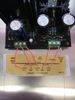
Yes the TT is grounded to the BB.If I short the input to ground the hum gets worse than when its open.(Shouldnt it dissapeare when shorted?)
the only difference from the old trafo is (when there was no hum) that I now have 9,5-0-9,5v , wheras before I had 9,5-0v .Could that have sommething to do with it?
the only difference from the old trafo is (when there was no hum) that I now have 9,5-0-9,5v , wheras before I had 9,5-0v .Could that have sommething to do with it?
Do you mean the input RCA's? If so they shouldn't be grounded at all, they should insulated from the chassis. Just the separate grounding lead from the TT should be earthed to the BB chassis
yes it is as you describe it.But I do not use shielded cable to the RCA´s just twisted leads..
And it is only in MC mode,not MM..
And it is only in MC mode,not MM..
Last edited:
What I mean is that the actual female RCA input connectors fitted to the BB chassis should be electrically insulated from the chassis.
I'm assuming you are using a one box setup. if so, have you tried moving the transformer outside the chassis and connecting with longer wires.
Have you used the HV centre terminal to ground the PCB to the chassis?Yes the TT is grounded to the BB.If I short the input to ground the hum gets worse than when its open.(Shouldnt it dissapeare when shorted?)
the only difference from the old trafo is (when there was no hum) that I now have 9,5-0-9,5v , wheras before I had 9,5-0v .Could that have sommething to do with it?
If you have take it off. If you haven't, ground the PCB to chassis.
Not every Turntable needs the ground wire attached. I get hum with it attached here, yet at my mates house, he needs it in the same Phonostage.
I have tried everey grounding options I can think of,but it always gives more hum.Yes the TT is grounded to the BB.If I short the input to ground the hum gets worse than when its open.(Shouldnt it dissapeare when shorted?)
the only difference from the old trafo is (when there was no hum) that I now have 9,5-0-9,5v , wheras before I had 9,5-0v .Could that have sommething to do with it?
So thought I´ll desolder one end of the 9,5-0-9,5v and try to only use 9,5-0.
And see the hum dissapeared...how com?
But the filamnet are within -10% of the value so I guess I cold run like this,If no one have any other suggestions?
I tink I found the real cause of it all.I am taking AC to the VU meters from the filament AC.
If I remove that the hum goes avay with 9,5-0-9,5v connected I guess I´ll have to find another small trafo fo the VU meters.....busy night...
If I remove that the hum goes avay with 9,5-0-9,5v connected I guess I´ll have to find another small trafo fo the VU meters.....busy night...
I found a small trafo for the vU meters.
And to get read of the last hum I grounded the negative side of the filament.
And to get read of the last hum I grounded the negative side of the filament.
I found a small trafo for the vU meters.
And to get read of the last hum I grounded the negative side of the filament.
The filaments shouldn't be grounded. There is a voltage lift to preserve the cathode to filament rating, particularly for V3.
Where exactly did you apply the ground?
It was at the intake on the pcb,the hum stopped at least.
Edit: At what voltage is the kathode of V3?
Edit: At what voltage is the kathode of V3?
Last edited:
If you have earthed the centre connection of the HV terminals that's fine.
V3 cathode is generally +120 to 130V
V3 cathode is generally +120 to 130V
a couple of questions for the wise,
what order do the transformer wires go in the green blocks and also which is the + for the led's, square of circular pad?


what order do the transformer wires go in the green blocks and also which is the + for the led's, square of circular pad?


Last edited:
- Home
- Source & Line
- Analogue Source
- Bigbottle Phonostage Builders thread
