Thanks Elvee,
I was worried about finding 2N3019, but I located them.
So off to jlcpcb with gerbers.....
I was worried about finding 2N3019, but I located them.
So off to jlcpcb with gerbers.....
Dear Mr Prasi,
You seem to be from India. Does JLC takes charges in Indian Rupees and approx transportation charges to India. Thanks
You seem to be from India. Does JLC takes charges in Indian Rupees and approx transportation charges to India. Thanks
Hello,
Yes, I am from India.
you may better avoid jlcpcb if ordering from India, they charge in usd and the shipping option is DHL/Fedex which is quite costly.
you may like check your options here
PCBShopper – A Price Comparison Site for Printed Circuit Boards
You might check out pcbway or elecrow for better prices including shipping
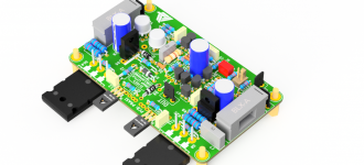
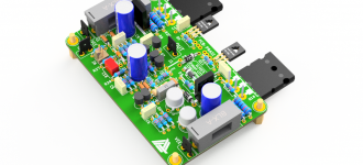
Just placed order for 10 proto @ relatively unknown board house ' smart prototyping'
Component fitment looks spot-on in 3D. placed order with RS for components that were not in bin like MBR745, film caps, BAT86 and some others.
Component fitment looks spot-on in 3D. placed order with RS for components that were not in bin like MBR745, film caps, BAT86 and some others.
Attachments
Last edited:
Dear Mr Elvee,
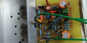
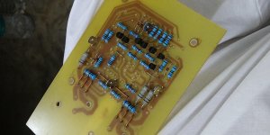
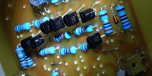
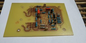
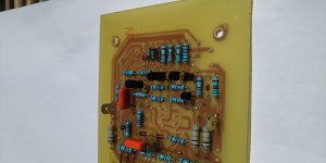
I have completed Circlophone as per Schematic at post#1. Mr Project16 designed PCB has been modified by me to accommodate TO3 2N3055 transistors. The PCB is made in two parts if TO3 is not needed than upper part can be detached. Following components have been used by me in this prototype build:
2N3055 - BEL India
BD139, BD140 - CDIL India
BC556 - CDIL India
2N5551 - KEC
VAS Transistors - 2SC 2621 Sanyo Japan (Pulled from my discarded colour TV (4.7 pf added between B&C)
BAT86 - SMD
Power Schottky - MBR 745 (Taiwan Semiconductors)
Polyster Capacitors - Philips
Resistors - Metal Film 1%
Electrolytic Capacitors - Keltron India
Other capacitors - MLCC
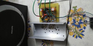
Mr Elvee I want to thank you for your efforts by offering us a wonderful amplifier. This amplifier is even working with 14-0-14 V transformer without distortion and crystal clear sound, rich in Bass. 2N3055 moderately heated. VAS very little heat.
Again accept my personal thanks for sharing wonderful design. I am sharing pictures of my prototype.
Thanks
Katiyar
I have completed Circlophone as per Schematic at post#1. Mr Project16 designed PCB has been modified by me to accommodate TO3 2N3055 transistors. The PCB is made in two parts if TO3 is not needed than upper part can be detached. Following components have been used by me in this prototype build:
2N3055 - BEL India
BD139, BD140 - CDIL India
BC556 - CDIL India
2N5551 - KEC
VAS Transistors - 2SC 2621 Sanyo Japan (Pulled from my discarded colour TV (4.7 pf added between B&C)
BAT86 - SMD
Power Schottky - MBR 745 (Taiwan Semiconductors)
Polyster Capacitors - Philips
Resistors - Metal Film 1%
Electrolytic Capacitors - Keltron India
Other capacitors - MLCC
Mr Elvee I want to thank you for your efforts by offering us a wonderful amplifier. This amplifier is even working with 14-0-14 V transformer without distortion and crystal clear sound, rich in Bass. 2N3055 moderately heated. VAS very little heat.
Again accept my personal thanks for sharing wonderful design. I am sharing pictures of my prototype.
Thanks
Katiyar
Pictures left now attached
Attachments
-
 IMG_20210605_183614_BEAUTY.jpg425.8 KB · Views: 394
 -
 IMG_20210521_201154_BEAUTY.jpg441.4 KB · Views: 367
 -
 IMG_20210521_201436_BEAUTY.jpg804.5 KB · Views: 364
 -
 IMG_20210521_201638_BEAUTY.jpg760.7 KB · Views: 201
 -
 IMG_20210523_101916_BEAUTY.jpg369.3 KB · Views: 215
 -
 IMG_20210523_102020_BEAUTY.jpg907.5 KB · Views: 202
 -
 IMG_20210605_183441_BEAUTY.jpg454.2 KB · Views: 215


My pleasure, thanksMr Elvee I want to thank you for your efforts by offering us a wonderful amplifier. This amplifier is even working with 14-0-14 V transformer without distortion and crystal clear sound, rich in Bass. 2N3055 moderately heated. VAS very little heat.
Again accept my personal thanks for sharing wonderful design.
@katiyar, nice build. Welcome to the club.
Starting from a couple weeks past, I put my MOSFET build on the table again in order to play with compensation values in hope to find a better scheme. Because I noticed overshoot issue with standard compensation values in Ltspice so I wanted to confirm it.
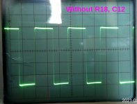
I played with different resistor values at three different places (LTP, VAS, Feedback Resistor) but returned to the Elvee's proposed values except VAS. When I completely discard the compensation network at this section, I got most clean square waves. I'm listening couple weeks then and nothing seems alarming regarding stability issues. Also sinus waves looks razor sharp on my 20Mhz analog oscilloscope.
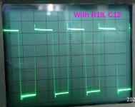
Photos taken at near clipping, 45V rails, IRFP240 hexfets, 2SA1370 VAS. The one with overshoot is R18=270, C12=180p. Different values of C12 show similar behavior.
I also tested power handling, it goes up to the 100W region easily.
Edit: Square wave photos taken at 10KHz. At 1KHz vertical lines aren't apparent at all.
Starting from a couple weeks past, I put my MOSFET build on the table again in order to play with compensation values in hope to find a better scheme. Because I noticed overshoot issue with standard compensation values in Ltspice so I wanted to confirm it.
I played with different resistor values at three different places (LTP, VAS, Feedback Resistor) but returned to the Elvee's proposed values except VAS. When I completely discard the compensation network at this section, I got most clean square waves. I'm listening couple weeks then and nothing seems alarming regarding stability issues. Also sinus waves looks razor sharp on my 20Mhz analog oscilloscope.
Photos taken at near clipping, 45V rails, IRFP240 hexfets, 2SA1370 VAS. The one with overshoot is R18=270, C12=180p. Different values of C12 show similar behavior.
I also tested power handling, it goes up to the 100W region easily.
Edit: Square wave photos taken at 10KHz. At 1KHz vertical lines aren't apparent at all.
Attachments
Last edited:
Another one from Dr. pcb! 🙂Just placed order for 10 proto @ relatively unknown board house ' smart prototyping'
Component fitment looks spot-on in 3D. placed order with RS for components that were not in bin like MBR745, film caps, BAT86 and some others.
Mr Thimios,
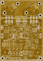
As desired, PDF file of final layout attached. Layout is 1:1 in A4 size which can be directly printed for PCB. There is little cosmetic change in board layout from my prototype but electrically and functionally there is no change. However you may again check it with schematic posted at Post #1.
Thanks
Katiyar
Attachments
come on Dr. DIYA, you can afford second 'cheap' ciclophone,' if you already own one!
Last edited:
Thimios, I'm itching as well, I have a couple, not as many as you ! I want to build a special one.I have a Slewmaster that is suprbb and will be hard to replace, but I have beautiful meters an such stuff for a beaut . I'm still deciding on a leach or something else with fets. I like a lot of power so that the amp can idle. Damm. choices, too many choices ! lol
Last edited:
Mr Elvee,
Based on the comments of Mr terranigma I changed the value of C12 from 820pf to 270 pf I have found that 2N3055 are producing less heat now. The quiescent current seem to have reduced. Could you please advice whether the Cirlophone has shifted its operation to Class AB only. I did not fing any noticable change in the quality odf sound. Low mid and high frequency are as before the change.
Based on the comments of Mr terranigma I changed the value of C12 from 820pf to 270 pf I have found that 2N3055 are producing less heat now. The quiescent current seem to have reduced. Could you please advice whether the Cirlophone has shifted its operation to Class AB only. I did not fing any noticable change in the quality odf sound. Low mid and high frequency are as before the change.
Trouth is that i haven't any ciclophone yet....come on Dr. DIYA, you can afford second 'cheap' ciclophone,' if you already own one!

Mr Elvee,
Based on the comments of Mr terranigma I changed the value of C12 from 820pf to 270 pf I have found that 2N3055 are producing less heat now. The quiescent current seem to have reduced. Could you please advice whether the Cirlophone has shifted its operation to Class AB only. I did not fing any noticable change in the quality odf sound. Low mid and high frequency are as before the change.
Elvee seems busy for a while so let me give you a tip until he arrives. Measure the voltage across the 1ohm resistor (R8) in milivolts range, it is the exact value of the quiescent current in miliamps. From my experience it should be between ~160 and ~200.
Regarding C12, you should use an even lower value like 180pF with 2N3055's. (read post #56).
- Home
- Amplifiers
- Solid State
- ♫♪ My little cheap Circlophone© ♫♪