Its time shall come 🙂
I have it disassembled again - need to change the way the whole z-axis moves. Still learning with each iteration...
Detail of the z-axis -
Hi mbat,
you shoul really consider adding a second rail to the z axis as one alone would be prone to deformation from torsion along the rail axis, even if it is just another right next to it.
Too late 🙂
I considered that several times - two rails require very high precision and there comes a whole new bunch of problems. I should also add that this machine is for milling XPS only - actually I think it's a bit of an overkill even as it is now.
I considered that several times - two rails require very high precision and there comes a whole new bunch of problems. I should also add that this machine is for milling XPS only - actually I think it's a bit of an overkill even as it is now.
Last edited:
I have seen this before but unfortunately I still have no clue what's wrong. Usually it helps to change the mesh grid somehow (perhaps generating fewer splines / points per spline, I don't know).
BTW, is this really what you want? The 'marto8' doesn't look like a proper waveguide at all, more like a mediocre direct-radiating dome tweeter. Number 2 is definitely closer to what I would choose.
Marcel,
Thanks for your suggestion!
I uploaded the wrong picture (too many modelling!). This is the one that wont import to fusion 360.
Attachments
That's quite nice. In a box it will get better regarding the directivity in the lower half of the passband (the DI will rise a bit) and at the same time there will be some more diffraction due to the box edges (that should be rounded, if possible).
Is it rectangular? I ask because if it was circular (axi-symmetric), the import to Fusion could be made differently and much more easily.
Is it rectangular? I ask because if it was circular (axi-symmetric), the import to Fusion could be made differently and much more easily.
Then please see the post #5083
- Ah, now I see it's actually not axisymmetric, so the above won't work, sorry.
Well, you can always import the STL file... It won't make a smooth surface but for 3D printing this is irrelevant anyway. High enough mesh resolution should work just fine. (I only don't know how to make it solid.)
- Ah, now I see it's actually not axisymmetric, so the above won't work, sorry.
Well, you can always import the STL file... It won't make a smooth surface but for 3D printing this is irrelevant anyway. High enough mesh resolution should work just fine. (I only don't know how to make it solid.)
Last edited:
Just a few remarks on the script you posted, I quickly skimmed through -
1) I don't understand why you have the mesh resolution so coarse - this won't work. Use the commented lines instead (and maybe decrease the *Resolution items a bit to properly capture the details of the geometry).
Mesh.AngularSegments = 100
Mesh.LengthSegments = 48
Mesh.CornerSegments = 48
Mesh.ThroatResolution = 48
Mesh.MouthResolution = 48
;Mesh.AngularSegments = 100
;Mesh.LengthSegments = 36
;Mesh.CornerSegments = 4
;Mesh.ThroatResolution = 3
;Mesh.MouthResolution = 9
2) The value Offset = 33 in ABEC.Polars is too small, i.e. still behind the baffle (that's the reason why you don't see the far off-axis angles calculated properly). You should set it to something bigger than 50 mm, which is the depth of your waveguide.
Marcel,
My mistake, I sent the file with "coarse" mesh as I was testing if it make a difference on Fusion 360 regarding the error I am getting when importing. It did not make any difference.
About the offset, yes... I remember reading your recommendation in prior post (or was it in the PDF? IDK) but I am aware of it.
I will import the STL and fin a way to add a 1-3/8 18TPI thread for my compression driver and test it.
Thanks for your help!
It seems that the Slot.Length item brings some new problems overall. I will have to reconsider how to implement it.
(This is the waveguide mga2009 designed.)
(This is the waveguide mga2009 designed.)
Attachments

Last edited:
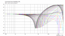
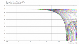
Driven by mode 0,1 (horizontal/vertical and diagonal polars).
Attachments
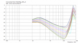
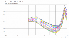
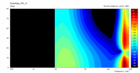
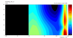
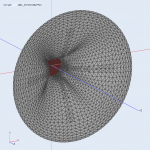
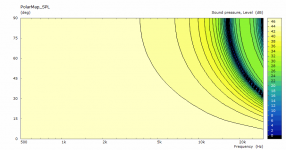
As a possible sanity check I made a simulation of a 1" flat disc in an infinite baffle, set to the mode 0,1 alone. Does it look sane?
Attachments


Last edited:
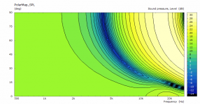
This is for a flat amplitude across the disc (i.e. mode 0,0 - all weights set to 1 in the above setup). This seems sane enough to me.
Attachments
Last edited:
That looks like what one would expect.
Mode 0,1 where 0 is the center of the membrane and 1 is the perimeter right?
Mode 0,1 where 0 is the center of the membrane and 1 is the perimeter right?
Last edited:
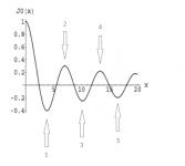
I don't follow. 0 means it's axisymmetric and the second index defines how large portion of the Bessel function (J_0 in this case) is mapped as the pressure (velocity) amplitude across the membrane. Value n means up to the n-th point where the Bessel function has zero slope (see the picture attached).
Attachments
I would agree that what you show looks right. I might have expected les radiation right on axis, but I can see how there is some.
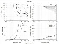
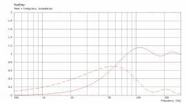
Re impedance… the imaginary part of the WG impedance makes somehow the phase between pressure and particle velocity will not be 0 degrees. It is thus analogous to the phase difference between current and voltage in a reactive electrical system. Electrical voltage corresponds to acoustic sound pressure and electric current corresponds to acoustic particle velocity. In a resistive system, current and voltage are in phase, ie also sound pressure and particle speed.
If the throat area of the horn is designed in a suitable way, ie as if it were linear with a suitable reactance, decreasing towards higher frequency and the driver is designed as a reactance, increasing with higher frequency (speed controlled instead of mass controlled) - when these two reactive quantities go in each direction and cancel each other out, the combination becomes resistive where the phase difference is zero between current and voltage.
If the impedances of the horn and the driver where each others opposite it would probably be a very advantageous situation i.e. a non reactive system yielding very low distorsion. Perhaps we need to look closer of how to match driver and WG when it comes to impedance (Real & Im) in order to reach the ultimate transducer?
//
First, there is no such thing as "speed controlled." A device is either compliance controlled, resistance controlled, or mass controlled.
While your idea may have merits in theory, in practice it is unworkable. Impedances are the result of a design and generally not something that we design around. You will likely find that inverse matching the impedances results in an unusable system. But this idea does sound a lot like the old idea of "reactance nulling" which can work for very low frequency devices, but is generally not suitable in higher frequency devices.
While your idea may have merits in theory, in practice it is unworkable. Impedances are the result of a design and generally not something that we design around. You will likely find that inverse matching the impedances results in an unusable system. But this idea does sound a lot like the old idea of "reactance nulling" which can work for very low frequency devices, but is generally not suitable in higher frequency devices.
As a possible sanity check I made a simulation of a 1" flat disc in an infinite baffle, set to the mode 0,1 alone. Does it look sane?
Hi Mabat,
I did not follow the entire discussion regarding the propagation of higher-order modes in horns, but your picture reminded me of the graph from Bjorn Kolbreck's master's thesis.

The picture is from Bjørn Kolbrek, Modal sound propagation in curved horns of rectangular cross-section
Hardly anyone has studied in more detail the modes propagation in horns problem than Bjorn. Probably it makes sense to look through his master and phd thesis in more detail, if you interesting in the modes propagation problem.
Last edited:
- Home
- Loudspeakers
- Multi-Way
- Acoustic Horn Design – The Easy Way (Ath4)