The performance (30dB improvement) of the denoiser is stated for a typical voltage of 15V. It will slightly degrade for lower voltages, and improve for higher voltages, but it will remain essentially functional.
If you want to use it at voltages <5V, I recommend you scale all the resistors values accordingly: it will keep the performances nominal
If you want to use it at voltages <5V, I recommend you scale all the resistors values accordingly: it will keep the performances nominal
Thanks Elvee!
That's a perfect advice and as a minimum a good starting point for trying a 5V PSU! Sounds like you've done it. Did you?
That's a perfect advice and as a minimum a good starting point for trying a 5V PSU! Sounds like you've done it. Did you?
I'm getting ready to put a few of these together. I've found buried in my parts box an Antek AS-0518, 18V, 50VA transformer, I'm not sure where it came from, but it has an extra purple wire, which shows in the specs as connected to...the core itself? What is this? What should I do with it, if anything? Thanks for any help!
You paid a little extra money to get an AS-0518 , the alternative AN-0518 is a little cheaper.
The S in the part number indicates that transformer has an electrostatic Shield between the primary winding and the secondary winding. It reduces coupling between the two windings, which reduces the amount of noise injected from the mains (primary) to the secondary. The shield inside the transformer is connected to the purple wire which runs outside the transformer.
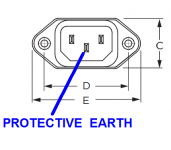
Connect the shield to the Protective Earth wire of the AC mains, i.e., the center wire of the IEC inlet, the one which is neither Line nor Neutral. Probably it is connected to your Chassis Ground. You can route the transformer shield wire to the Chassis Ground and connect it to Protective Earth there.
_
The S in the part number indicates that transformer has an electrostatic Shield between the primary winding and the secondary winding. It reduces coupling between the two windings, which reduces the amount of noise injected from the mains (primary) to the secondary. The shield inside the transformer is connected to the purple wire which runs outside the transformer.
Connect the shield to the Protective Earth wire of the AC mains, i.e., the center wire of the IEC inlet, the one which is neither Line nor Neutral. Probably it is connected to your Chassis Ground. You can route the transformer shield wire to the Chassis Ground and connect it to Protective Earth there.
_
Attachments
Thanks for that. Oddly enough, it seems that all the 50VA Antek transformers are "AS", which probably explains how I ended up with it.
Not for a real application, but I tested voltage extremes during my evaluationsSounds like you've done it. Did you?
Hi Folks,
I need some help on VDRN board. It worked very well for few weeks until yesterday electricity outage. The positive rail voltage floats from 3-4 volts (slowly) regardless on the pot setting, LM317 radiator gets super hot within few seconds from powering in up and I can smell burning electronics (just a little).
However, I cannot spot what element causes the trouble - all looks fine visually.
The situation is the same with J3 open/close.
Thanks in advance for any suggestions.
When mains power is restored after outage, very nasty voltage spikes could happen. It is good practice to switch off or disconnect all sensitive equipment until power is restored and stable.
It’s hard to believe that such voltage spike has reached LM regulator and caused damage, but it is not entirely impossible.
Disconnect load from the regulator and check if there is any change. If there is no change, try replacing the LM317 regulator.
It’s hard to believe that such voltage spike has reached LM regulator and caused damage, but it is not entirely impossible.
Disconnect load from the regulator and check if there is any change. If there is no change, try replacing the LM317 regulator.
Fellas,
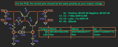
I am building 2 of these supplies and silly me neglected to order a pair of BC327’s for Q2 in my last Mouser order.
If any of you have a pair, please PM.
Alternatively would BC550C/560C combination work for Q1/Q2?
Kind regards,
Anand.
I am building 2 of these supplies and silly me neglected to order a pair of BC327’s for Q2 in my last Mouser order.
If any of you have a pair, please PM.
Alternatively would BC550C/560C combination work for Q1/Q2?
Kind regards,
Anand.
Last edited:
I have a couple I can send you.
Alan
Alan
Fellas,
I am building 2 of these supplies and silly me neglected to order a pair of BC327’s for Q2 in my last Mouser order.
If any of you have a pair, please PM.
Alternatively would BC550C/560C combination work for Q1/Q2?
Kind regards,
Anand.
I'm building Wayne's BA2018 line stage, and I'm powering it with dual-mono VRDN boards. I've got a single 25VA 18V (115v) transformer for each board (so two total), and I'm trying to figure out:
-what fuse value and type to use between the switch and the transformer - I've calculated 320 mA as a fuse value (25VA/115V*1.5) but want to know if this is correct or if I've missed something. I found 315mA slow blow standard fuses at Mouser.
-do I need any other sort of in-rush current protection for these boards between ac mains and the transformers?
-do I need any sort of current protection between the VRDN outputs and the BA2018 inputs?
Would prefer not to start any fires, tiny or otherwise, so I appreciate any help you can give.
Thanks,
Brad
I run mine with one vedn, 2x15V 50VA and haven’t even spent attention to the fuse (there is one, but probably 1A or whatever).
No inrush limiter and no current-protection. Runs wonderfully…
No inrush limiter and no current-protection. Runs wonderfully…
@bpr, yes I'd buy a slow blow fuse in the vicinity of 250-350mA. No inrush limiter needed and in truth, no other protections needed. The LM317 & LM337 include protection circuitry already.
I run mine with one vedn, 2x15V 50VA and haven’t even spent attention to the fuse (there is one, but probably 1A or whatever).
No inrush limiter and no current-protection. Runs wonderfully…
@bpr, yes I'd buy a slow blow fuse in the vicinity of 250-350mA. No inrush limiter needed and in truth, no other protections needed. The LM317 & LM337 include protection circuitry already.
Thanks to you both!
Basically, two main possibilities: wrong measurement (you shouldn't be able to measure anything in the mV range before or after the cap-mult, you'd need a microvoltmeter equipped with a good LNA to see something), or wrong GND connection system: if your GND is polluted to start with, you won't get rid of the noise by simply stacking up noise-reducing systems.I connected a capmultiplier after the denoiser and got higher ripple,how come?
Without c capmulti ,8mv pk-pk with c cap 12mv...
The core problem should be addressed first.
Anyway, placing a cap-mult downstream of the VRDN is the worst configuration possible: the cap-mult will ruin the noise performance and the output impedance of the VRDN. It will in theory reduce the ripple, but the initial ripple would need to be rather large to make a difference, otherwise the ripple will be drowned in the noise anyway.
A much better option is to place the cap-mult upstream of the VRDN: you will gain the improvement in ripple rejection, but keep the low noise and low output impedance afforded by the VRDN/Denoiser.
The penalty of additional dropout will remain the same.
In the denoizator thread, Trileru has examined various configurations, and posted some results
- Home
- Amplifiers
- Power Supplies
- VRDN: bipolar regulator PCB for line level ckts: ±11V to ±20V @ 1.5A with "De-Noiser"