Triad PSU jack won't fit 2.5mm. PJ-037b connector
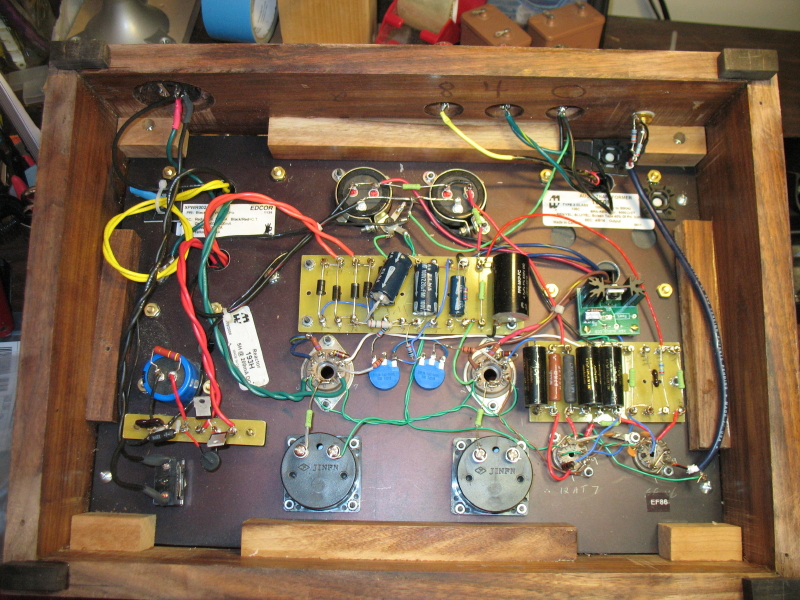
ACP+ is all dressed up and ready to go and the PSU won't fit.
I used a good bit of force just short of unseating the power con and no go. I really don't want to have to hard wire the sumbitch.
Mouser 490-pj-037b power con is installed with 2.5mm. pin.
Triad WSU240-0500 Spec sheet reads 2.5mm. barrel plug.
Speaking of power...the switch as spec'd from the BOM is on/on? Huh? The circuit makes one side OFF?
Can someone save me from looking through 155 pages?
Last edited:
It seems there are two transformers with similar part numbers:
Triad WSU240-0500 has 2.1mm barrel while Triad WSU240-0500-13 has 2.5mm.
http://www.farnell.com/datasheets/2279808.pdf
https://www.mouser.ca/datasheet/2/410/WSU240_0500_13-1893086.pdf
Triad WSU240-0500 has 2.1mm barrel while Triad WSU240-0500-13 has 2.5mm.
http://www.farnell.com/datasheets/2279808.pdf
https://www.mouser.ca/datasheet/2/410/WSU240_0500_13-1893086.pdf
Datasheet I found for that PSU shows 2.1mm.
https://assets.alliedelec.com/v1558002201/Datasheets/fa54b09713db1a718b2fdde9d6f65e2f.pdf
re: the switch - if you use the correct switch, and if you wire it correctly, you're good.
Edited to add - Just what Dennis said.... he types faster. 😀 😀
https://assets.alliedelec.com/v1558002201/Datasheets/fa54b09713db1a718b2fdde9d6f65e2f.pdf
re: the switch - if you use the correct switch, and if you wire it correctly, you're good.
Edited to add - Just what Dennis said.... he types faster. 😀 😀
This worries me a bit looking into my future build. There are no good local suppliers of resistors. Local availability is just kid's-projects type of resistors, very poor quality.
Has anyone received the store's Parts Kit already? Are there any "spare" resistors to try to achieve this 10mA or is it so case-by-case that there is no way but to measure and buy the appropriate values?
That is going to be one expensive set of resistors for me if that is the case 🙁 .
Thanks for any feedback,
Rafa.
I also bought the kit. It came out perfectly! I assumed they put the correct r4 in there.
Datasheet I found for that PSU shows 2.1mm.
https://assets.alliedelec.com/v1558002201/Datasheets/fa54b09713db1a718b2fdde9d6f65e2f.pdf
re: the switch - if you use the correct switch, and if you wire it correctly, you're good.
Edited to add - Just what Dennis said.... he types faster. 😀 😀
Appreciate the replies.
I'll have to look up the Triad PSU with the -13 suffix while I G-nash my teeth over another incorrect part number, or one omitted from the rather sketchy BOM. The power con is a cheap part so I guess I'll look for one with a 2.1mm barrel rather than buying another expensive PSU.
As regards, the switch, it dawns on me that a DPDT On-On that fits into 6 eyelets is an input selector, not a power switch. (Face, meet palm) The PSU power cord will need an on-off switch unless I want to go always on.
I hope you guys that buy the kit fare better than those of us who worked off the documentation here to date.
My latest of a parade of builds from schematics done point-to-point had fewer frustrations except those I brought upon myself.
Correct Digikey Power Con Part Number
You may want to wait until it arrives but I just ordered PJ-037B with a 2.1mm. pin to match the Triad TRIAD WSU240-0500.
Part: $0.59
Shipping: $4.99
Cheaper than another PSU.
You may want to wait until it arrives but I just ordered PJ-037B with a 2.1mm. pin to match the Triad TRIAD WSU240-0500.
Part: $0.59
Shipping: $4.99
Cheaper than another PSU.
Great news! Thanks! Can you comment which value resistor you installed in R4?
Rafa - you can solve that with trimpot in place of resistor, connected as variable resistor
Hopefully you ordered some more previously - once when you are bitten with this bug, buying various parts in advance becomes regular praxis
Yes, that is the plan. I have a project in Mouser called "spare parts bin", and I am going to include all this "spares" in there and make one single import. I'll perhaps abuse of your generosity and shoot you a PM with what you think are the "basics". I haven't thought of trip pots, for example, but makes a lot of sense.Rafa...Hopefully you ordered some more previously - once when you are bitten with this bug, buying various parts in advance becomes regular praxis
I have none. There are none available locally. Anything needs to be imported. But it doesn't make sense to import two resistors, or one trim pot. A whole bunch of resistor values, trim pots, cable, plugs, etc. That would make sense. So yes, that is the plan, let's see what needs to be included there.
Thanks for all the help, as always!
Rafa.
to RafaPolit #1550
Hello RafaPolit,
I have used a trimpot together with a resistor (50 Ohm trimpot - 25turn + 47 Ohm resistor). So I could easily adjust the correct current through the CCS (J113).
Later you can desolder and measure the resistance of the resistor-trimpot - combo
and can replace with one resistor.
Cheers
Dirk 😀
Attachments
Yes, that is the plan. I have a project in Mouser called "spare parts bin"...
Let me know what resistor values you need once you've figured it out and I'll send some in a small padded envelope. PM me when you do...

Great news! Thanks! Can you comment which value resistor you installed in R4?
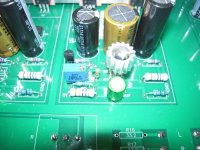
Just checked, Mine has 125 ohm Dale in that position. The J113 measured 3.04V each on my test jig using 12v and 100 ohm resistor.
I just not sure how to determine the resistance to create the 10 ma needed here. I have plans to build another and a pile of J113s now. Actually I would be happy to match up some and pass them along if I could figure it out!
I almost have my acp+ wrapped up. The default J113 and 127ohm R4 resistor gave the following:
Left - 0.813 (6.40ma)
Right - 0.806 (6.34ma)
Quick swap of R4 to 47.5ohm and I have ended with the following:
Left - 0.495 (10.42ma)
Right - 0.488 (10.27ma)
Is that right in the 10ma ballpark? or should I get both channels closer?
Thanks
Def close enough. In fact, try listening with lower CSS levels and see what happens. 😉
--Tom
Just checked, Mine has 125 ohm Dale in that position. The J113 measured 3.04V each on my test jig using 12v and 100 ohm resistor.
I just not sure how to determine the resistance to create the 10 ma needed here. I have plans to build another and a pile of J113s now. Actually I would be happy to match up some and pass them along if I could figure it out!
They don't really need to be matched per se, you just need to adjust R4 to pass 10 mA of current.
You can check this in the circuit using ohm's law. Just measure the voltage across R4 and use Ohm's law in the form
I= V/R
(where V=measured voltage across R4,
R= resistance of R4)
to calculate the current, I, through R4.
I started my ACP+ build with socketed trimpots in R4 to make it easy to find the correct values.
FWIW, I ended up with about 40R in one channel and 45R in the other. But YMMV
billyk,
To check the J113 in place, measure the voltage drop across R4. Then use Ohm's Law to determine the current.
V = I x R, therefore I = V/R.
If your R4 is 125 Ohm and the measured voltage drop across R4 is 1.25V, then I=1.25V/125 Ohm = 0.010A, or 10mA.
So measure the voltage drop and do the calculation I = V/R. If the current is less than 10mA, decrease the resistor value and re-measure and calculate. If the current is greater than 10mA, increase the resistor value and re-measure and calculate. Repeat until the current is at or close to 10mA, say between 9,5 and 10.5mA.
To test and sort J113 and match to resistors for 10mA at 12V, you need a 12VDC source (battery or power supply) and connect it to this circuit:
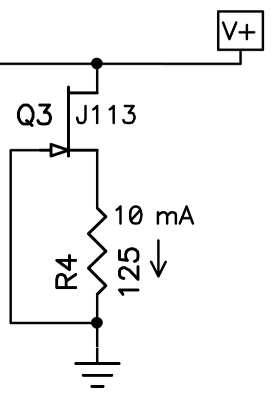
In place of the 125 Ohm resistor, put in a trimmer pot and a 20 Ohm resistor in series. Adjust the trimmer until 10mA flows through the 20 Ohm resistor. Again, Ohm's Law: V = 0.010A x 20 Ohm = 0.20V. The value of R4 is the sum of the trimmer resistance and 20 Ohm. The 20 Ohm resistor value is not critical except that if it is too high, you may not get 10mA through some samples of J113.
To check the J113 in place, measure the voltage drop across R4. Then use Ohm's Law to determine the current.
V = I x R, therefore I = V/R.
If your R4 is 125 Ohm and the measured voltage drop across R4 is 1.25V, then I=1.25V/125 Ohm = 0.010A, or 10mA.
So measure the voltage drop and do the calculation I = V/R. If the current is less than 10mA, decrease the resistor value and re-measure and calculate. If the current is greater than 10mA, increase the resistor value and re-measure and calculate. Repeat until the current is at or close to 10mA, say between 9,5 and 10.5mA.
To test and sort J113 and match to resistors for 10mA at 12V, you need a 12VDC source (battery or power supply) and connect it to this circuit:
In place of the 125 Ohm resistor, put in a trimmer pot and a 20 Ohm resistor in series. Adjust the trimmer until 10mA flows through the 20 Ohm resistor. Again, Ohm's Law: V = 0.010A x 20 Ohm = 0.20V. The value of R4 is the sum of the trimmer resistance and 20 Ohm. The 20 Ohm resistor value is not critical except that if it is too high, you may not get 10mA through some samples of J113.
Great thank you. Testing in circuit! I should have thought about that. Thank you kindly everyone.
Let me know what resistor values you need once you've figured it out and I'll send some in a small padded envelope. PM me when you do...
Thanks so much! This community is so great! I have a PM with the same offer. You guys are simply the best.
It is precisely our countries Mail Office that went bankrupt and we cannot send even the smallest letter without huge risk of losing it / never getting it. So we resolve to curriers that bring packages, but they have a minimum value, no matter the package. So, a small letter would still be $40. So I just need to figure out the proper value, and include that in a bigger order of more things.
If I have need of your generosity, I'll reach out. Thanks so much.
Rafa.
Hello RafaPolit,
I have used a trimpot together with a resistor (50 Ohm trimpot - 25turn + 47 Ohm resistor). So I could easily adjust the correct current through the CCS (J113).
Later you can desolder and measure the resistance of the resistor-trimpot - combo
and can replace with one resistor.
Cheers
Dirk 😀
Very useful! Thanks. And I would need to de-solder? To measure? Can't I measure in-circuit the combined resistance of the two and order the part, but keep this in until parts arrive?
I'm curious as to why would it not measure in-circuit if I'm measuring resistance across a single resistor (obviously I know nothing about this, please forgive me if this is obvious).
Thanks,
Rafa.
You're not measuring resistance. You're measuring voltage across the resistor. That can only be done if the circuit is powered on--either in a test jig, or on the actual PCB.
But yes, after you have the right voltage/resistance combination to equal 10mA you can desolder and measure the resistance so that you can order one resistor of the right value.
I'm no expert but I wonder if leaving the pot in place wouldn't be ok too.
But yes, after you have the right voltage/resistance combination to equal 10mA you can desolder and measure the resistance so that you can order one resistor of the right value.
I'm no expert but I wonder if leaving the pot in place wouldn't be ok too.
- Home
- Amplifiers
- Pass Labs
- Amp Camp Pre+Headphone Amp - ACP+