Thanks atmasphere for elaborating.
As you indicate, internal tube shorts appear to be related to shedded cathode coating, and I would add to that also dangling/melted grid wiring such as from an over-heated screen, and cathode-heater shorts. The concern I have with this thread's circlotron design is the use of two power transformers that each supply B+ to one side and screen for the other side - which may make for a screen meltdown if only one power transformer fuse blew.
As you indicate, internal tube shorts appear to be related to shedded cathode coating, and I would add to that also dangling/melted grid wiring such as from an over-heated screen, and cathode-heater shorts. The concern I have with this thread's circlotron design is the use of two power transformers that each supply B+ to one side and screen for the other side - which may make for a screen meltdown if only one power transformer fuse blew.
Thanks atmasphere for elaborating.
As you indicate, internal tube shorts appear to be related to shedded cathode coating, and I would add to that also dangling/melted grid wiring such as from an over-heated screen, and cathode-heater shorts. The concern I have with this thread's circlotron design is the use of two power transformers that each supply B+ to one side and screen for the other side - which may make for a screen meltdown if only one power transformer fuse blew.
Yes, if it were mine to do I would have the screen and plate supplies on the same transformer.
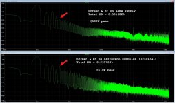
I have been taking time to simulate failure modes, as suggested, and I have also recognized this to be a significant issue. The screens on one phase bank would immediately exceed their dissipation limits upon loss of the complementary PSU. The original Kimmel design has the screens set up this way because it appears to allow one to squeeze more power out for a given input. I don't think this is worth the risk, and as I recently found might not even be necessary in the first place.
I did an LTspice comparison of the original screens/B+ on separate supplies versus screens/B+ on same supplies. The THD in the original topology is lower, but the 5th order harmonics are significantly higher at all power levels. The same-supply topology has higher THD, lower max power, higher 3rd order, but far lower 5th order.
I think the answer is clear here: it's safer and better sounding to keep phase supplies together on separate, fused transformers.
Attachments
Interesting.
A 3rd is benign like the 2nd and its good to have it be high enough to mask higher orders. A prominent 5th isn't good- that is one of the objections that the SETs guys are always on about and for good reason.
A 5th is suggesting that you have both a quadratic and cubic non-linearity at the same time.
If you can, a single power transformer is safer. If using two transformers, one fuse can fail and then the amp pushes DC. If there are dual windings on a single transformer it will simply fade out.
Oops when I said two transformers I was mistakenly talking about the separate audio channels. The two phases for a single channel are indeed on the same transformer. I was looking at my in-progress schematic and spoke out of context of the present conversation.
To reiterate: the two phases of the single audio output channel operate off isolated floating supplies derived from a single fused transformer. Sorry for the brief confusion.
To reiterate: the two phases of the single audio output channel operate off isolated floating supplies derived from a single fused transformer. Sorry for the brief confusion.
Soft-Start and Bipolar PSU boards nearly complete
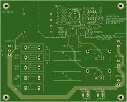
After taking some time to evaluate necessary safety measures, I'm in closing in on a final design for the soft start circuit + AC distribution board. It contains the soft start delay circuit, primary fuses, and terminal blocks to connect to all the transformers. The circuit uses an NE555P timer to bypass surge-limiting thermistors with an optocoupler-controlled TRIAC. The timer circuit is run independently with its own transformer, and has a bypass delay of ~250ms.
Before submitting the order for the PCB I will test the soft start circuit to make sure it performs the same as the simulations.
I also finished testing the maida-style regulator for the bipolar 150V supply, and confirmed that it behaves as designed. I will submit the PCB order once the soft start board is also confirmed.
On the to-do list is find the right DC offset speaker protection circuit to implement. There are a lot of low-cost kits on ebay that look promising, but I need to figure out which ones would actually work with the circlotron output topology.
As I revisit and revamp each module, I am getting closer to completing the comprehensive schematic. I will post it soon once I polish up the remaining modules.
Attachments

On the to-do list is find the right DC offset speaker protection circuit to implement. There are a lot of low-cost kits on ebay that look promising, but I need to figure out which ones would actually work with the circlotron output topology.
Just as a FWIW, if one side of the Circlotron is +high, the other side wants to be an equal minus voltage. So you really only need to look at one side of it to know if a DC voltage is present.
Given the soft-start functionality, the fuses may benefit from tweaking to the lowest value consistent with actual measured operational current, and also be fast not slo-blow.
The pcb designators don't align with the schematic designators for the NTCs. Are the NTC's capable of operating continuously (ie. fail safe for loss of triac function)?
It's also common to fuse the mains input of a module such as this, or alternatively fuse all circuits connected to the mains.
The pcb designators don't align with the schematic designators for the NTCs. Are the NTC's capable of operating continuously (ie. fail safe for loss of triac function)?
It's also common to fuse the mains input of a module such as this, or alternatively fuse all circuits connected to the mains.
FWIW, i built a Tim Mellows OTL and for speaker protection i used an output coupling cap, there are are no turn on/off thumps anyway...for soft starting CL60 NTC resistors are sufficient....
Speaker Protection Circuit
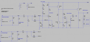
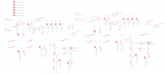
After some research and tinkering I decided it would be more fun to attempt to build the speaker protection circuit instead of buying a module off eBay. Borrowing from some existing designs and substituting some changes of my own, I have a circuit that seems to simulate correctly.
The circuit features DC offset detection down to 1.55V, which is enough to detect a significant imbalance (the loss of multiple tubes or an entire phase) and swiftly remove the speakers. Any higher voltages result in even faster turn-off characteristics. AC is passed down to 5Hz at full power without triggering.
There is also a turn-on delay and AC power-off mute function built in.
The relay is a pair of source-connected mosfets controlled by an isolated diode emulator, the Si8752. There will be one solid-state relay per channel, both controlled from the single detection circuit.
Still waiting on my parts from the other modules to come in so I can test the current designs before ordering the PCBs.
Attachments
Inrush current limiter and fuse test
Got the parts for my soft start circuit and did some quick bench tests. I hooked up a completed output module board to the 500VA isolation toroid and put the 15R/12A Thermistor and 2.5A fast fuse in series with the hot side of the primary. This configuration is representative of the turn-on condition for one output channel.
The thermistor worked perfectly and the 2.5A fuse didn’t blow. Without inrush limiting the toroid would normally pull more than 40A peak. I monitored the voltage drop across the thermistor during inrush and it dropped to about 1V after 5 seconds or so. The thermistor is rated for continuous operation, and would do its job fine if the triac fails. It’s still safer long-term to bypass it and let it cool down in between startups.
At maximum continuous power output I expect each output power toroid to pull at most 2.25A RMS on the primary side, so the fast blow fuse of 2.5A should give enough headroom while also keeping the response fast in a failure situation.
I appreciate the advice from this thread a lot. It’s definitely elevated this project beyond what it might have been otherwise.
Schematics for PCB mostly finalized
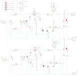
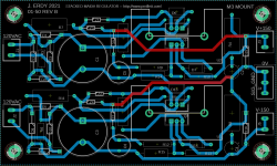
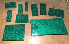
I've been taking my time with the PCB designs, making double sure that I don't overlook any stupid mistakes before I fab them. Currently I have 5 PCBs that will be going into the amplifier chassis (designated as 01-), and one into the power supply chassis (designated 02-):
I will probably sit on the designs for another day or two before ordering, might make a few more tweaks. I've attached below images of the amplifier chassis EAGLE boards and schematics. They are all two-layer boards that I will be sending to JLCPCB.
I've been taking my time with the PCB designs, making double sure that I don't overlook any stupid mistakes before I fab them. Currently I have 5 PCBs that will be going into the amplifier chassis (designated as 01-), and one into the power supply chassis (designated 02-):
- 01-10 REV B Output Module: this is the power supply for the output tube bank.
- 01-50 REV B Bipolar PSU Module: the +/- 150V volt supply for the bias and A2 driver board
- 01-60 REV A DC Filament Module: the preamp is high gain, and I was getting noise in the prototype and DC filaments are an easy addition
- 01-80-10 REV A Output Terminal Module: Connects directly to the speaker binding posts. Has hookups for output, NFB, and DC offset detection.
- 01-80-20 REV A DC Detect Module: DC offset sensing and protection trigger circuit. This will activate a SSR to disconnect the speakers if there is any significant DC imbalance.
I will probably sit on the designs for another day or two before ordering, might make a few more tweaks. I've attached below images of the amplifier chassis EAGLE boards and schematics. They are all two-layer boards that I will be sending to JLCPCB.
Attachments
-
 01-80-20 REV A DC Detect Schematic.png95.7 KB · Views: 151
 -
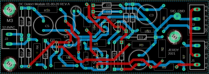 01-80-20 REV A DC Detect Module.png78.4 KB · Views: 142
 -
 01-80-10 REV A Output Terminal Schematic.png48.5 KB · Views: 151
 -
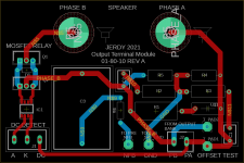 01-80-10 REV A Output Terminal Module.png62.4 KB · Views: 154
 -
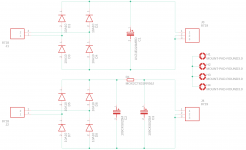 01-60 REV A DC Filament Schematic.png34.9 KB · Views: 136
 -
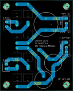 01-60 REV A DC Filament Module.png79.6 KB · Views: 168
 -
 01-50 REV B Bipolar PSU Schematic.jpg346.8 KB · Views: 413
 -
 01-50 REV B Bipolar PSU Module.png89 KB · Views: 410
 -
 01-10 REV B Output Schematic.png175.9 KB · Views: 421
 -
 01-10 REV B Output Module.png311.9 KB · Views: 439
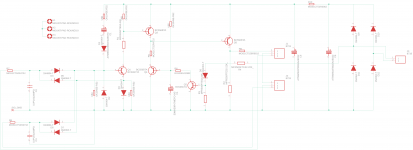
Jerdy, I'm not sure about the connection to C8/C19 as that cap takes rectifier pulses that have to pass back through C1/C14 and the big bridge, whereas you have the rectification current pulses going to the next RC filter stage (eg after R1/R2 and R9/R10) - same goes for R4/R12 bleeds.
Jerdy, I'm not sure about the connection to C8/C19 as that cap takes rectifier pulses that have to pass back through C1/C14 and the big bridge, whereas you have the rectification current pulses going to the next RC filter stage (eg after R1/R2 and R9/R10) - same goes for R4/R12 bleeds.
I see what you mean. Some spice simulations show that moving the negative terminal of the doubler supply cap and bleed resistor to the first filter cap keeps the charging current from running through the 10R resistor. Not a huge impact, but would reduce voltage ripple and improve current balance between the two 10R resistors. I have incorporated this change into REV C.
Attachments

PCBs Ordered
Well, I pulled the trigger on the PCBs. 10 in total, which represents all the remaining modules (plus one redo). Prototyping and verifying the new modules was the slowest part, but things accelerated once I started on the previously vetted circuitry. As soon as JLCPCB finishes my order, things are really going to start moving.
Well, I pulled the trigger on the PCBs. 10 in total, which represents all the remaining modules (plus one redo). Prototyping and verifying the new modules was the slowest part, but things accelerated once I started on the previously vetted circuitry. As soon as JLCPCB finishes my order, things are really going to start moving.
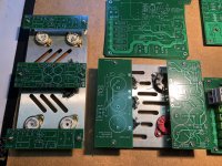
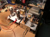
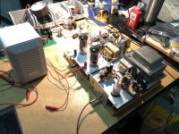
PCBs Arrive, assembly begins
The boards arrived today, much quicker than I anticipated. There are 10 modules in total, so I have a lot of work ahead of me. I got a start this evening on the soft-start module, and I did some dry fitting of the breakout boards for the preamp audio section and preamp PSU.
Originally, when this project was conceived 3 years ago I assumed I would do point-to-point wiring on the tube sections since all my sockets on-hand were solder lug terminated. However, once I learned how to design PCBs in EAGLE that plan changed. Now I've migrated most of the components onto breakout boards that can interface with the tube sockets. Next time I'm just going straight for PCB tube sockets...
While I was waiting for my boards, I actually had some time to whip up a compact little OTL using 6LB6 tubes. Just two tubes can make 1 Watt audio power without too much distortion, which might make for a nice bookshelf speaker project. But first things first: I've got to finish my Big OTL!
Attachments

OTP in Circlotron
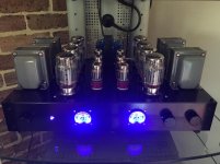
I built a Circlotron using 4x EL509-II per channel and a low turns ratio output transformer mounted at the speakers. The money you save on tubes can buy you some nice Lundahl LL1627 output transformers. It wont heat the room too much, doesn't require lots of negative feedback (mine is zero global FB), can use bell-wire for speaker cables, wont fry your speakers if there is an anode-cathode short, and it sounds great.
I built a Circlotron using 4x EL509-II per channel and a low turns ratio output transformer mounted at the speakers. The money you save on tubes can buy you some nice Lundahl LL1627 output transformers. It wont heat the room too much, doesn't require lots of negative feedback (mine is zero global FB), can use bell-wire for speaker cables, wont fry your speakers if there is an anode-cathode short, and it sounds great.
Attachments
I built a Circlotron using 4x EL509-II per channel and a low turns ratio output transformer mounted at the speakers. The money you save on tubes can buy you some nice Lundahl LL1627 output transformers. It wont heat the room too much, doesn't require lots of negative feedback (mine is zero global FB), can use bell-wire for speaker cables, wont fry your speakers if there is an anode-cathode short, and it sounds great.
Are those new production EL509s? I did save money scrounging tubes, but all that savings is going into the other system components such as the PCBs and eventually the chassis. The original design goal was a directly-coupled Circlotron output, so I’m going to try and preserve that. However, I want to do a build eventually where I can splurge on an nice OPT; maybe a nice DHT SET since I haven’t done that yet. All my previous projects used repurposed OPTs of varying quality 😀
The method I’m using for speaker protection is an active DC offset protection circuit controlling a mosfet relay on the speaker connection. I tested it the other day and it worked as designed, will post some update pictures in my next progress dump 🙂
Also, beautiful build BTW. Love to see it!
Last edited:
- Home
- Amplifiers
- Tubes / Valves
- 100 Watt sweep tube Circlotron OTL (WIP)