You´re welcome. I like to skip the kiss for now😉
Just to be sure I meant if fits your case as in your purpose not the actual case/enclosure so if you decide to use that PCB be sure it fits.
Also, it doesn´t hurt to ask if anybody has leftover PCBs. I´m sure many had them produced for themselves.
I also got "leftovers" from a fellow forum member.
Seems to work perfectly! Simulation is with a 120R load on the end that's just obscured by that notification. I'm making an integrated PCB so no need to worry about it fitting in my case. 😀


Have decided to go SMPS in the end.It is surprising to see many favor SMPS but then accept the high noise and ripple and use an extra filter. It seems a bit like cutting a finger deliberately and then search for a bandaid. In your case the casing forces the choice but why are SMPS so in favor? Serious question as I see mostly trouble like HF/RF radiation (which the output filter won't solve) etc. with the vast majority of those. Again in this case one needs linear regs to get the situation as it should be for good audio... Is it the fear for mains voltage that shifted the preferences? Or is best possible quality not a goal, just "good enough"? Or is self built stuff not measured ?
Some others observing such an issue:
https://www.diyaudio.com/forums/eve...mps-killed-radio-reception-2.html#post6676807
As for why SMPS units are becoming popular, as far as I know it's because its far less dangerous to use a wall wart and then a DC/DC converter to get the voltage(s) you want rather than having to screw around with live voltages, as you said. Using a mains SMPS unit is just as dangerous as dealing with a LPS but in that case its due to space considerations: not needing a gigantic case is very much a plus in my book!
Best way is to
1) measure the spectrum of the noise on the PSU so you know where the switching frequency and its harmonics are
2) check the filter's frequency response in spice and tune it to get good attenuation there
For this you need to add the parasitics, especially the ESR/ESL of caps, and if you want to trust it above 5MHz you need proper inductor models. Most power inductors have SRF below 5MHz anyway, so if at step 1 you got significant noise above that, you'll need to add ferrite beads.
If you add a regulator, then its PSRR and the rejection of the filter make a good complement because PSRR falls at HF whereas inductors get more effective.
The suggestion for LDO's was because of that.
BucketInAbucket, thanks for the answers. However, I see mains voltages as an essential part of the audio hobby and also make very small devices with LPS. All my experiments and measurements with many linear and SMPS were in favor of LPS. I think no one likes large devices anymore in this day and age. Since I have seen fires caused by always on equipment my forced choice is that a 230V mains switch is a hard requirement just like I want to know what electrolytic caps are used. So no wall warts and no molded in PSU's. In practice unattended wall warts being powered on 24/7 is a much higher risk than wiring a transformer IMHO but tastes/opinions may vary.
BucketInAbucket, thanks for the answers. However, I see mains voltages as an essential part of the audio hobby and also make very small devices with LPS. All my experiments and measurements with many linear and SMPS were in favor of LPS. I think no one likes large devices anymore in this day and age. Since I have seen fires caused by always on equipment my forced choice is that a 230V mains switch is a hard requirement just like I want to know what electrolytic caps are used. So no wall warts and no molded in PSU's. In practice unattended wall warts being powered on 24/7 is a much higher risk than wiring a transformer IMHO but tastes/opinions may vary.
Last edited:
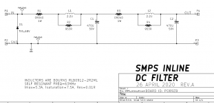
Notes about the filter board posted above:
Resistors in parallel with inductors are useless
50mOhm resistors are useless (you use the ESR of the cap to prevent ringing in the LC)
No SMD MLCCs, so bad HF performance
Poor layout maximizes capacitor ESL, so bad HF performance
No ferrites beads, so bad HF performance
No ground plane
etc
Resistors in parallel with inductors are useless
50mOhm resistors are useless (you use the ESR of the cap to prevent ringing in the LC)
No SMD MLCCs, so bad HF performance
Poor layout maximizes capacitor ESL, so bad HF performance
No ferrites beads, so bad HF performance
No ground plane
etc
Yes, lol.
Look up "Series RLC circuit damping factor"
Optimize ESR and value of capacitor to have damping factor >1 with inductor, and then you get no ringing.
Here with 10µH inductor and 100µF cap you need ~500mOhm ESR which means a series resistor is required, that's annoying.

Increase C and L requires lower R for damping, and gives better attenuation

Add ferrite bead (1k@100MHz) and 2x 1µF MLCC, plus a high ESR cheap alu cap on the output to damp ringing between bead and MLCC

That shouldn't break the bank...
USE A GROUND PLANE
Look up "Series RLC circuit damping factor"
Optimize ESR and value of capacitor to have damping factor >1 with inductor, and then you get no ringing.
Here with 10µH inductor and 100µF cap you need ~500mOhm ESR which means a series resistor is required, that's annoying.
Increase C and L requires lower R for damping, and gives better attenuation
Add ferrite bead (1k@100MHz) and 2x 1µF MLCC, plus a high ESR cheap alu cap on the output to damp ringing between bead and MLCC
That shouldn't break the bank...
USE A GROUND PLANE
Peufeu, this is essentially a filter by a known designer here. It is built by many and it is seen as the solution to the issues one gets with the choice for SMPS.

If you don't use a post-regulator then the low value 2.2µH inductor makes sense to get low output impedance across audio band. But OP wants to use a post regulator which means higher inductor value is not a problem, which means an extra 65dB attenuation at switching frequency (say ~40kHz) for about the same filter cost.
Ha ha how I love miscommunication 😀 It would have helped if the design goal was mentioned to be "good enough". I think it is clear that Peufeu and my humble person are in this stuff to obtain "best results possible at acceptable costs" if I may speak for Peufeu. "Good enough" is the category one can order ready made. In the eyes of many that pursue "best possible results" highest quality is the starting point only negotiable when costs are too high or a technical drawback compromises things.
As you have seen this way of thinking and designing clashes with the club that designs and builds stuff that has the "it works" status (which is also fine, whatever floats your boat).
As you have seen this way of thinking and designing clashes with the club that designs and builds stuff that has the "it works" status (which is also fine, whatever floats your boat).
Last edited:
If I can gain some knowledge in order to be able to optimize the design a bit then I'm all ears 😀
I do not think the 2 resonances of your filter in the audio band +11dB at 2kHz and 6k will do good for an audio application.
I advise to put 330mohm in series with each cap which will cure the problem and still attenuate 50dB at 100kHz
I advise to put 330mohm in series with each cap which will cure the problem and still attenuate 50dB at 100kHz
I am busy trying out different values in ltspice to try and get a circuit that is stable 🙂
Question, does the cut-off value actually matter? Or not?
Question, does the cut-off value actually matter? Or not?
Last edited:
The inductive kick on switch-on goes up to 19V with 100R load, that will kill eventually some op-amps. Important Zeners at the output.
You have to start the simul with 0V across the caps
The data sheet says 150mV ripple to 20MHz that would be reduced to less than 1mV
You have to start the simul with 0V across the caps
The data sheet says 150mV ripple to 20MHz that would be reduced to less than 1mV
Last edited:
Why don´t you post in the main thread for the P089B-filter instead of making BucketInABucket unnecessarily nervous? That would be very constructive and might help others/you to understand what´s really important and if the dampening resistors are actually needed.Notes about the filter board posted above:
Resistors in parallel with inductors are useless
50mOhm resistors are useless (you use the ESR of the cap to prevent ringing in the LC)
No SMD MLCCs, so bad HF performance
Poor layout maximizes capacitor ESL, so bad HF performance
No ferrites beads, so bad HF performance
No ground plane
etc
As I said, I only know Traco but you´d hard pressed to get a similar performance from a linear power supply in a reasonable size.
You´ll need lots of capacitance and regulators to get anywhere near.
I often use them for testing purposes without any LC-filter and that is mainly line level circuitry.
Go ahead and do it! I´d dare say you´ll be absolutely fine and if not, you can always add some extra filtering. It will still be much smaller than a comparable regulated linear power supply.Seems to work perfectly!
No that is an assumption. Apart from the size (it is indeed a challenge to make linear stuff as small as possible) the specifications can be/are way better with careful analog design. It is a HPA and not a power amplifier so current draw is not extreme. Also constant current draw because of the class A behavior which makes it simpler in a way with CLC and LDO regulators.
I think it is in many cases allowing to get used (or being forced professionally) to the easier/cheaper way and then defend the choice by stating the positive features which mainly have nothing to do with excellent performance, then compensate with an absolutely necessary added filter to solve issues introduced by choice.
I think it is in many cases allowing to get used (or being forced professionally) to the easier/cheaper way and then defend the choice by stating the positive features which mainly have nothing to do with excellent performance, then compensate with an absolutely necessary added filter to solve issues introduced by choice.
Attachments
Last edited:
Safe to say that with these specs, it is more than adequate 🙂 inductors and resistor add about 0.79R to the output which should still be manageable.

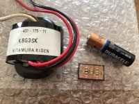
Inductors are SRN1060-101M, caps are Panasonic EEU-FC1J221. R7 was necessary as otherwise it'd result in resonances and decreased performance.

Inductors are SRN1060-101M, caps are Panasonic EEU-FC1J221. R7 was necessary as otherwise it'd result in resonances and decreased performance.
Last edited:
Ha ha how I love miscommunication 😀
Damn! Marketing changed the project requirements again 😀
>"best results possible at acceptable costs" if I may speak for Peufeu
Yes
- Home
- Amplifiers
- Power Supplies
- Filtering after encapsulated AC/DC module