Here are photos of the commercial products "M2" and "F5" sold by First Watt, at a price around USD 3500 per amplifier. M2 has one trimmer potentiometer per channel and F5 has two trimmers per channel. They appear to be the very same trimmer potentiometers used by hundreds of DIYers in the Amp Camp Amp. If so then you could check the official ACA parts list to find out which trimmers are approved and blessed by the engineers who make the decisions at First Watt.
_
Yes, I have noticed that FW amps use a lot of the Bourns single turn trimmers. Also Korg uses the single turns. I think also Pass Labs uses them? Most other FW clones like M2X like to use the multi turns.....
VFET it the hottest amp I yet have built. So lot of hot air inside. It could influence the stability of the Bourns (heating up/cooling down)?
However until now it is only a theory that it is the trimmer that is the "issue". But right channel trimmer seems more sensitive to generate noise as only a very slight touch creates noise in speaker (but only very low noise.....nothing to disturb listening experience). Also that it can suddenly stop so also R-speaker is dead silent. And then suddenly noise can come back. Most people will never notice as the preamp noise will probably be predominant.
Could be interesting to hear Mr. Pass if he has ever discarded a Bourns single turn trimmer (I have not yet but close to discard my first trimmer 🙂 )?
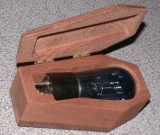
I will keep the trimmer and if it was not the issue "Mr. trimmer" will get an excuse....and I can put him in a very fine box 🙂
Mr. Pirsig had written few interesting pages about stuck screw, on side cover plate

Oh, I love that book!
😱 30€+TVA per trimmer! Why? Are them so special?
Precision and stability, price..well is a business 😀
Attachments
Bourns trimmers are used throughout the factory built Pass Labs and Firstwatt products.
The only verified advantage the expensive trimmers have is the ability to make your wallet lighter.
The only verified advantage the expensive trimmers have is the ability to make your wallet lighter.
..Also that it can suddenly stop so also R-speaker is dead silent. And then suddenly noise can come back. Most people will never notice as the preamp noise will probably be predominant.
I am very curious why this is happen..
anyway good luck,
two silent channels all the time
is better for enjoyment with the music 🙂
If it was 1/f-noise from VFET we would expect noise to be fairly constant and not suddenly stop?
If I unsolder the trimmer and measure a value for two resistors and install these resistors we will have the answer.
None of the two trimmers are silent during adjustment but you won't hear it from speaker unless you have 110 dB speakers or so. I can hear it from distance because I have a battery driven amp with built-in speaker connected to speaker binding posts on amp. Seems to be a simple way to check noise from amp.
But again......amp is silent.....it is not just always "dead-silent" in R-channel.
Maybe I have "worked" the trimmer so much that it is less noisy like when you work a vol-pot on an old amp.....noise gets less when vol-pot is "worked" a bit (cleaning of the resistive element......often carbon on these old amps).
I've had a 100K Bourns trimmer display similar behavior from being 'worked' too much, for what it's worth.
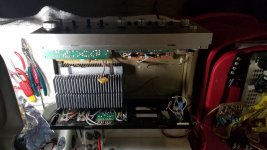
Continuing to spitball Sony TA 4650 chassis. After gutting power supply, looks like plenty of room for Meanwell internal PS @ 36V and various cards, and another 20v power for built in preamp. Putting 20v variable power supply onto preamp leads, preamp sounds great through headphones on preamp output for such an ancient device. It looks like simple two stages of FET cascode. Keeping it alive allows the use of many of the inputs and tone controls, and amp can be accessed independently if desired through power amp input. Heat sink is unknown, but I think the heat sink should work with the 68 (??) watts of dissipation for two channels.
I guess I will enter second auction and see if I have any luck, and, barring that, wait for later card iterations based on types 2SK60 or 2SJ18. These have half the anode power dissipation of the favored 2SJ28 devices, but look like they could still output around 5-10 watts of Class A power.
If I can make one chassis that works, then I could use the second TA 4650 chassis to include an internal B1 Korg card as well.
Attachments
Just a couple of tips for builders:
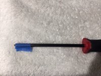
(1) When bolting the Front End PCBs to the heatsinks + threaded standoffs, I find it helpful to temporarily "attach" the M3 bolt to the screwdriver head. Now I can fit it into tight spaces much smaller than fat fingers allow. And believe me, there are some tight spaces when mounting Marauder and Dreadnought to the heatsink! See attached photo. A bit of masking tape holds the bolt head to the screwdriver shaft. After screwing it in two or three complete rotations, I just pull the screwdriver away and remove the tape. Then finish tightening.
(2) When working in confined spaces with plenty of obstacles, I prefer to use a flexible shaft screwdriver like this one on Amazon. Now I can curve the shaft to put the bit where I want and the handle somewhere else that's roomier. It helps a lot when mounting the front and rear panels to the heatsink rails, for example.
_
Attachments
CJ. I'm not sure if everything is in it's final position, but you may find better cooling if you turn the heat sink casting 90 degrees so that the fins/gaps align with the slots/gaps in the casing base. Just as they are in the original setup. You may have to make a couple of brackets I suppose, but I think that it would pay dividends on cooling performance like that.
Regards.
R
Regards.
R
Yeah, those are just in there for scale. I will try the original configuration first. If Temperature of heat sink with VFETS turned on is too high, then I can consider second heat sink or other options. There is time to play with it. Some aluminum heat chimneys might be in order, too. It appears from the use of one heatsink with six vfets in the TAN 8550 that each heatsink is designed for 100 watts or more of dissipation, but I will watch and see. There is plenty of room in there.
Thank you for your input.
Thank you for your input.
Last edited:
That sounds like a good plan. I would say the 100w figure is based on class AB output. Your earlier statement of 5 to 10 W seems right to me. If one looks at the latest NP Vfet kit, (size, number and position of heat sinks and output power) that is probably a good indicator. Would it be possible to use a variable speed fan and thermocouple on startup, altering bias and winding the fan down eventually if the temp is ok? I have a dead TA-4560 and look at your design with interest. Thanks.
Hi, Jotom,
This is my second DIY project ever, the first being the Korg preamp, which has been singing well for a while now.
So, I am not an expert on anything, much less heat sinks, so I am kind of feeling it as I go along. Fans are always possible, and ZenMod has good recommendations on various threads.
It used to be that you could get TA 4650 routinely in ebay for about $150 to $200 in the day in good working condition, so I used them at various times for surround channels, or preamp sections for bass control, or the amp stage for Stax headphones. I would also listen to them in stereo, but, of course, they are already old and they eventually crapped out in one way or another leaving the chassis. Sounded marvelous.
I don't want to restore vintage any more, I haven't had any that continue to work that well with the Sony VFET products, but I have entertained the notion of putting some form of new Pass DIY into the chassis as a kind of tribute to my years with VFET. So far, it looks quite do-able, but you can follow my failure or success or whatever before you try the same, it will unfold as NP and DIY store unfold the cards and parts after the auction feeding frenzy.
I gave my Korg a 50/50 chance of success and it worked out, so I will probably give this the same general odds.
Hi CJ.
Yes, I have a couple also, they were it seemed the less "loved" I think of the Sony Vfet range.
(Listening to a TA-5650 ATM) I'm hoping to find a good pre-amp design for the tiny vfets (79 or 63 is it?). It's an interesting project. regarding the variable fan, I only proposed that for initial set up and safety, but obviously it could be left in also. Thanks for your efforts 🙂
- Home
- Amplifiers
- Pass Labs
- DIY Sony VFET Builders thread