I had a idea about the help file. This is quite big these days and there is not a search function in it nor I can use the mouse wheel to scroll.
Hi kees,
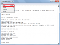
Select the File > Find menu commands or press Ctrl+F to access the Help file search function.
Visual Basic 6.0 does not have built-in support for mouse wheel scrolling. There is a work-around, but it requires the use of an external DLL, which I would rather avoid.
The Help file can be navigated a number of ways:
1. Use the vertical scroll bar on the right hand side.
2. Press the Page Up or Page Down key.
3. Press the Home or End key.
4. Double-click on any item in the Contents list to display that section of the file.
Kind regards,
David
Attachments
Understood on the first part.
<< Ports gone for 4-seg OD/OP: >>
The problem was inadvertently introduced with the release of Version 52.20, when the topology for an offset driver / offset port system with a closed rear chamber was changed. It will be fixed in the next update.
<< Any chance to treat an OP port like an ME throat and have flares? >>
It should be possible, unless I run into unforeseen problems along the way.
<< My dream would be to have that and be able to put a CH fronthorn on at the OD, too. >>
That is looking very much like "a bridge too far" at this stage... 🙂.
how can i show the max-spl for bandpass simulations?
You can't - maximum SPL functionality is not supported, and a number of other features available elsewhere are also missing.
Hello guys, and especially hello David! 🙂
In the last few days, i was simulating a couple enclosures for my subwoofer (mostly with WinISD).
I allways liked the idea of a 6th order serial tuned bandpass, wich was unable to simulate until now, when i finally found Hornresp!!!
But i am pretty confused, at what Hornresp outputs me, compared to WinISD
I got strange peaks in the result, so i simulated a simple closed box, to see, if atleast this looks familiar, wich was NOT the case.
When simulating a closed box, i get just 1 big peak as result, like the following picture shows:
I hope, you can help me 🙂
Thanks
Benni
I have done it also and does well, I get 78 liters total and this plot with a wsp26s from visaton.
David I did setup also the volume what pipe and speaker does take, I did discover that this does not much on these systems, but did include it.
How to set up a 6th order box with hornresp?.
thanks.
Attachments

Last edited:
The Help file can be navigated a number of ways:
Surprised you didn't mention the option you gave me, convert to WordPad with all its versatility; being able to enlarge it/change font for easy reading is a big help for me, so thanks again!
How to set up a 6th order box with hornresp?
If you are asking how to optimise a BP6 design in Hornresp, then that is up to you 🙂.
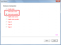
If you are asking how to specify a BP6 design in Hornresp, then:
1. Use the Input Wizard to create a representative design and then modify to suit.
2. Read the relevant section in the Help file.
Attachments
Surprised you didn't mention the option you gave me
I completely forgot about it 🙂. Pleased to learn that it has made life easier for you! Thanks for posting the information for kees and others.
Variation in calculated results for physically similar models?
Hello David,
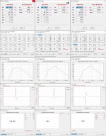
I was playing around, modeling flat open baffle with a 15" B&C coaxial, ending up with three models that are physically similar for all practical purposes but vary in acoustic output and impulse response. I attached a picture consolidated information of the three models. Please take a look.
Hello David,
I was playing around, modeling flat open baffle with a 15" B&C coaxial, ending up with three models that are physically similar for all practical purposes but vary in acoustic output and impulse response. I attached a picture consolidated information of the three models. Please take a look.
Attachments
I completely forgot about it 🙂. Pleased to learn that it has made life easier for you! Thanks for posting the information for kees and others.
 Finally rebooted with the larger display option ya'll pointed out, which made enough difference with HR that I no longer need my [heavy] high power half glasses crushing my nose and generally fatiguing me from eye strain.
Now all need is more time to learn all the new features starting with the multi-driver horn.
Please take a look.
If you change the record 4 path length from 89.1 cm to 28.2 cm and calculate the record 6 impulse response normally, not using Maximum SPL, then the results for records 5 and 6 will be identical and the results for record 4 will be only slightly different (because a horn rather than a direct radiator is being modelled in that case).
Record 5 is the correct way to simulate a direct radiator in a flat open finite baffle.
Last edited:
made enough difference with HR that I no longer need my [heavy] high power half glasses crushing my nose and generally fatiguing me from eye strain.
Excellent news 🙂.
If you change the record 4 path length from 89.1 cm to 28.2 cm and calculate the record 6 impulse response normally, not using Maximum SPL, then the results for records 5 and 6 will be identical and the results for record 4 will be only slightly different (because a horn rather than a direct radiator is being modelled in that case).
Record 5 is the correct way to simulate a direct radiator in a flat open finite baffle.
I'll check the results based on your suggestions and come back.
But in none of the cases, I specified the path length.
But in none of the cases, I specified the path length.
Path lengths for open baffle systems are calculated automatically. You created record 4 using the Input Wizard which gave you a flat open baffle with a default area of 10000 sq cm and a system path length of 89.1 cm. You then modified the record so that it became in effect a short horn rather than an open baffle, and the path length was no longer automatically calculated. In modifying the record you also reduced the area from 10000 sq cm to 1257 sq cm but didn't change the path length to suit your new design.
Rest assured, the Hornresp simulation models are working correctly 🙂.
Hello once more 🙂
While simulating an 8th order parallel bandpass, i encountered a problem.
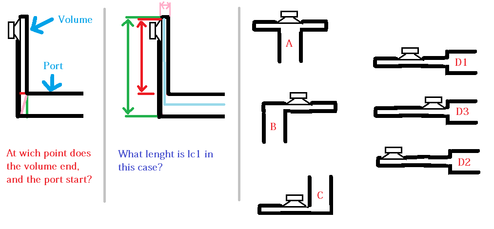
For the high tuned chamber it is absolutely important, to choose the right "lc1"
So, what is lc1, and how do i correctly build the chamber vs port.
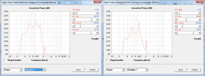
This is, how just halving the lc1 (80 to 40 cm) makes a difference:

Does lc1 has to be at a given location compared to the driver (opposite/ 90 to it/ at the wall wich contains the port)?
Is lc1 just the longest part between 2 walls inside the chamber?
Is lc1 the maximum path inside the chamber (diagonally corner to corner)
Another Question... does the driver location inside the chamber matter (at a corner/in the middle/ opposite of the port/ same side then port ...)?
And if so... wich location does hornresp assume, so i can build it like that in real?
The following pictures shows, what i need to know to figure the right lc1.
How should i build the box, to fit the right lc1 (wich seems pretty hard, bc it has to be high with a low volume).
Thanks again for your help 🙂
Benni
While simulating an 8th order parallel bandpass, i encountered a problem.
For the high tuned chamber it is absolutely important, to choose the right "lc1"
So, what is lc1, and how do i correctly build the chamber vs port.
This is, how just halving the lc1 (80 to 40 cm) makes a difference:
Does lc1 has to be at a given location compared to the driver (opposite/ 90 to it/ at the wall wich contains the port)?
Is lc1 just the longest part between 2 walls inside the chamber?
Is lc1 the maximum path inside the chamber (diagonally corner to corner)
Another Question... does the driver location inside the chamber matter (at a corner/in the middle/ opposite of the port/ same side then port ...)?
And if so... wich location does hornresp assume, so i can build it like that in real?
The following pictures shows, what i need to know to figure the right lc1.
How should i build the box, to fit the right lc1 (wich seems pretty hard, bc it has to be high with a low volume).
Thanks again for your help 🙂
Benni
Attachments

So, what is lc1, and how do i correctly build the chamber vs port.
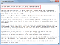
Lc1 is given on both the main input parameters window and the system model block diagram - see attachments. For the predictions to match measurements, the acoustic path of the system needs to follow as closely as possible that shown in the system model block diagram. For the purposes of the simulation, the chambers and ports are assumed to be cylindrical, connected "in-line".
Attachments
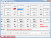
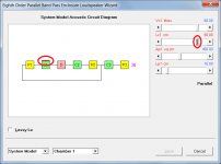
Lc1 is given on both the main input parameters window and the system model block diagram - see attachments. For the predictions to match measurements, the acoustic path of the system needs to follow as closely as possible that shown in the system model block diagram. For the purposes of the simulation, the chambers and ports are assumed to be cylindrical, connected "in-line".
Ok, if i get you right... lc1 is just the part from center of the speakercone to center of the port? No matter where i locate the port, no matter what the measurements of the chamber are?
So, in other words, if i want the biggest possible value for lc1, i would need to position the driver like the example D2 in my image?
Could you also tell me please, wich would be the correct lenght to match port and chamber.
In my example image left side... is it the red, pink or green line, wich would be the right border between port and chamber?
Thank you once more 🙂
lc1 is just the part from center of the speakercone to center of the port? No matter where i locate the port, no matter what the measurements of the chamber are?
Visualise the acoustic path from the centre of the driver diaphragm, though chamber 1 to the entrance to port tube 1. The length of that imagined path is then the value to use for Lc1. The value chosen for Lc1 will depend on the physical dimensions of chamber 1.
So, in other words, if i want the biggest possible value for lc1, i would need to position the driver like the example D2 in my image?
Yes.
Could you also tell me please, wich would be the correct lenght to match port and chamber.
Lc1 should be slightly shorter than the red line you show in the right side image - the path should start from the centre of the driver, not from the top of the chamber.
In my example image left side... is it the red, pink or green line, wich would be the right border between port and chamber?
To keep things simple, I would use the red line as the boundary - it will be close enough. Remember, we are dealing with bass frequencies here. A couple of centimetres' difference in Lc1 either way, will have little effect on the performance over the frequency range of interest.
Visualise the acoustic path from the centre of the driver diaphragm, though chamber 1 to the entrance to port tube 1. The length of that imagined path is then the value to use for Lc1. The value chosen for Lc1 will depend on the physical dimensions of chamber 1.
Thanks, then i finally know, what to take care of. I was just extremly unsure, bc i have seen different pictures, where people wrote lc at different places on the box borders.
Lc1 should be slightly shorter than the red line you show in the right side image - the path should start from the centre of the driver, not from the top of the chamber.
I realised that it should start from the center of the cone, a little bit later... 😀
To keep things simple, I would use the red line as the boundary - it will be close enough. Remember, we are dealing with bass frequencies here. A couple of centimetres' difference in Lc1 either way, will have little effect on the performance over the frequency range of interest.
Ok, that also helps me to have the maximum lc for chamber1. In fact, you can compare the 2 simulation, wich showed before. Since the chamber 1 is so small, it makes a huge difference, if lc is a couple cm longer or shorter.
In fact, it makes a difference between "just" 5 db peaks vs 12db peaks, and a usefull range up to ~170 Hz vs ~110Hz
Thanks for all the informations, this will help me a LOT!!! 🙂
In fact, you can compare the 2 simulation, wich showed before. Since the chamber 1 is so small, it makes a huge difference, if lc is a couple cm longer or shorter.
In fact, it makes a difference between "just" 5 db peaks vs 12db peaks, and a usefull range up to ~170 Hz vs ~110Hz
In the example you posted Lc1 was halved from 80 cm to 40 cm - that's a lot more than more than a couple of cm 🙂. If the value of Lc1 is actually as critical as you say, then perhaps for good design a larger chamber should be used.
Any chance to treat an OP port like an ME throat and have flares? My dream would be to have that and be able to put a CH fronthorn on at the OD, too.
Unfortunately it has proved to be just too much work to implement the above features in Hornresp.
Another one for AKABAK...
- Home
- Loudspeakers
- Subwoofers
- Hornresp