You have aroused my curiosity here! Looking at the data the ECL82 seems to have the better triode, but ECL86 was more used commercially, like in the Rogers Cadet III amp.
Rogers RD Cadet MK 3 Stereo Amplifier Circuit Diagram and Operating Manual | valve-radio.co.uk
How did you find them for sound quality? Did you prefer the EL86 - was it more powerful or the same?
Yes, the triode of the ECL82 is a more linear but the pentode needs more drive (approx. 2x the voltage for similar output power) so in the end they are pretty much equivalent.
I get 2W at 5% THD from an average PCL86, with Yugoslavian unbranded PCL86's I get almost 2.5W same distortion!
All running at 340V/23-24 mA with fixed bias into 8K nominal (in reality is a bit less around 7.7K). Because the bias for that current is between 11 and 11.5V and it was supposed to be an economical amp I derived the fixed bias from the same secondary that supplies the heaters at 14V. I take it in parallel with decoupling cap and then use a bridge and good filtering. Another cheap way to get it is the old trick o f back-bias where there is a CRC filter for the main plate supply and the the ground is at the second cap. This way the resistor will see the entire current of the amplifier providing a negative rail at the first cap negative end. For class A operation it works rather well as the total average current is pretty much constant until it gets close to clipping.
Next time I come to London I can bring the amplifier. This is the amplifier I have used most as I use it as backup amp in my office and work bench, more often connected to the radio and it now has somewhere between 20K-30K hours of operation....😀
"It would be a small room with speakers only a few feet away at fairly low listening levels. The current speakers are small and about 85dB I ran a DIY Push-Pull (PP) 6V6 / 6V6GT Tube Amplifier Schematic"
If power is enough: just triode-strap the amp you have, and leave out nfb. I did the same with a slightly evolved version of your circuit, and am living happily ever after.
If power is enough: just triode-strap the amp you have, and leave out nfb. I did the same with a slightly evolved version of your circuit, and am living happily ever after.
In my situation (98db/w, 4x4m room, 2,5m from speakers) there's power to spare: 11 o'clock is loud.
From UL to triode I changed nothing other than the screen connection. 😉
From UL to triode I changed nothing other than the screen connection. 😉
Really, it's relatively easy to make a good sounding 5W PP triode amp.
6A3sUMMER's simple design is similar to a couple of other well-liked amps like Poindexter's Musical Machine and Eli Duttman's El Cheapo (and El Cheapo Grande).
Can you see the family resemblence? 😉
The same basic circuit with 8k OPTs can use PP EL34-triode, 6L6GC-triode, 7591A-triode, 6P1P-triode, 6V6GT-triode, or EL84-triode.
If I was to try the music machine with the power supply shown here:

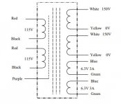
would this transformer work for the B+ and heaters:
Outputs 4x
Power 100VA
Output Voltage Current
150V 0.33A
150V 0.33A
6.3V 3A
6.3V 3A
with the 150v output paralleled
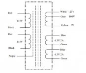
and this for the -140 and 12.6 supply:
Output Voltage Current
120V 0.2A
6.3V 2A
6.3V 2A
with the 6.3V in series
Attachments
Are you looking at Antek transformers?
You don't have to use a voltage doubler. I think Poinz did that because he wanted to use a cheap transformer he happened to have.
To get roughly +300V DC you can use a 460VCT (230-0-230) power transformer, or a single 230VAC secondary with a full-wave diode bridge. (That's 230VAC under load.)
These numbers are all going to be approximate. You will need to adjust parts values to get the exact voltages you need from any transformer.
Your proposed 150V 100VA transformer with its two 150V secondaries in parallel will be capable of 330mA current (with a voltage doubler). That's far more than you need, which would be perfectly fine.
250V * 200mA = 50VA
A bigger than needed transformer with a light load will supply higher than expected voltages, but you can compensate for that in various ways. It's much more difficult to squeeze higher voltage out of a transformer than what it was designed for than it is to burn off a few extra volts.
Antek makes a 280V 50VA (with 260V tap) rated for 200mA, with 6V secondaries.
Last edited:
I'm not locked into antek for the power transformers, they have them readily available and less expensive than hammond.
I forgot about the voltage being higher with an overrated transformer.
I forgot about the voltage being higher with an overrated transformer.
That particular power trafo runs about 440 V no load and 360 V at full DC load (160 mA, 60 watts) with cap input filter. I would ditch the doubler, just to make life easier on the caps. Dropping voltage on a class A design is easy. Class B has to deal with the swing in applied DC voltage. The Anteks are a very good value for the money - the only real issue people have with them is they are butt-ugly compared to most other solutions. Some people put a metal can around them - often costing much or more than the transformer itself. They do have a belly band around them, eliminating the “need” for a can for shielding. But that’s part of the reason they’re not so pretty. They do run cool, so they can be internally mounted in many cases.
That’s a full wave doubler and won’t result in DC in the core. It does result in 60 Hz ripple rather than 120 and much poorer power factor compared to a 4 diode bridge. But the secondaries can be wired in series so it’s not needed. You CAN use two caps like with a doubler if the connection between them is connected to center tap. That lets you use two 250 volt caps.
A full wave doubler has 120Hz ripple on its DC output, but neither it or a classic "full wave rectifier" (2 diode valves in a single bottle, 5something4, etc.) is as efficient as a 4 diode bridge. Sometimes handy when worrying about pushing the rating of old milsurp transformers.
All good fortune,
Chris
All good fortune,
Chris
Since we're on the subject, and I haven't found a direct answer to the question, what happens when you take a transformer with a center-tapped secondary and rectify it with a full-wave bridge, leaving the center tap disconnected? (This is with the negative-going diodes grounded -- not a bi-polar supply.) Do you get a higher rectified voltage from it, or just the same DC voltage out but with slightly more current capacity?
Attachments
Last edited:
Member
Joined 2009
Paid Member
if you bridge rectify across the full secondary with one output of the bridge grounded, the other giving B+, then the centre tap gives you around half B+.
But what is the value (in DC volts) of B+?
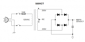
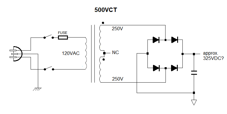
If the secondary is 500VCT, and you put a full-wave bridge as shown in the schematic attached to my previous post (across the entire secondary with negative output grounded), then is the positive DC output 500VAC * 1.414, or is it 250VAC * 1.414?
(I suspect it is 250VAC * 1.414, just like the full-wave rectified secondary with grounded center tap, but without the copper and iron losses of the transformer -- but I don't understand why that is so.)
Last edited:
A full wave doubler has 120Hz ripple on its DC output, but neither it or a classic "full wave rectifier" (2 diode valves in a single bottle, 5something4, etc.) is as efficient as a 4 diode bridge. Sometimes handy when worrying about pushing the rating of old milsurp transformers.
All good fortune,
Chris
But the doubler has 60 Hz ripple in the capacitors, even though it’s 120 on the DC output. That’s harder on the capacitors. Higher ripple current at a lower frequency. The doubler is harder on the transformer than either the 2 diode center tapped full wave or a 4 diode bridge with higher RMS current in the windings. Gotta pay for all that voltage somehow.
Since we're on the subject, and I haven't found a direct answer to the question, what happens when you take a transformer with a center-tapped secondary and rectify it with a full-wave bridge, leaving the center tap disconnected? (This is with the negative-going diodes grounded -- not a bi-polar supply.) Do you get a higher rectified voltage from it, or just the same DC voltage out but with slightly more current capacity?
That’s a classic 4 diode bridge, the most efficient kind of rectifier aside from the 3 phase version. If you only use “half” of it, with the negative pair not used, and ground from the center tap (like a classical full wave vacuum rectifier) you only get 70% of the transformer’s capacity compared to the 4 diode bridge. RMS current goes up by another factor of the square root of two. Think about it - only half the secondary is connected at any given point in time - so half of it is contributing nothing at all times.
Sorry for being slow but...
Is that 70% of the transformer's voltage capacity?
Or 70% of its current capacity?
Does that pertain to the grounded center tap situation only, or to the full-wave diode bridge with grounded negative half as well?
I'm sorry for being so confused. Some things just don't sink in easily for me.
Thanks.
If you only use “half” of it, with the negative pair not used, and ground from the center tap (like a classical full wave vacuum rectifier) you only get 70% of the transformer’s capacity compared to the 4 diode bridge.
Is that 70% of the transformer's voltage capacity?
Or 70% of its current capacity?
Think about it - only half the secondary is connected at any given point in time - so half of it is contributing nothing at all times.
Does that pertain to the grounded center tap situation only, or to the full-wave diode bridge with grounded negative half as well?
I'm sorry for being so confused. Some things just don't sink in easily for me.
Thanks.
OK, I think I got it now.
Differences between Full Wave Bridge & Center Tapped Full Wave Rectifier
Using a transformer with 500VCT 200mA secondary, if you use the center tap grounded and two diodes for full wave rectification the PIV of the diodes will need to be 2 times the voltage across the secondary (so >1000V rated diodes required for the 500VCT secondary). Also, the maximum load current before the transformer saturates will be 0.693 of the transformer's full current load rating (0.2A * 0.693 = 0.139A).
Using the same transformer with 500VCT 200mA secondary, if you leave the center tap disconnected and use a four diode full wave bridge with negative end grounded, the PIV of the diodes will need to be the same as the voltage across the secondary (so >500V rated diodes required for the 500VCT secondary). Also, the maximum load current before the transformer saturates will be 0.812 of the transformer's full current load rating (0.2A * 0.812 = 0.162A).
In both cases the DC output voltage will be 2Vm/pi or 2*500V/3.14159 = 318V DC
I sure do hope that's right, so this thread can get back to the original topic. 😱
But what is the value (in DC volts) of B+?
If the secondary is 500VCT, and you put a full-wave bridge as shown in the schematic attached to my previous post (across the entire secondary with negative output grounded), then is the positive DC output 500VAC * 1.414, or is it 250VAC * 1.414?
If you don't connect the center tap to ground then that is a 500VAC winding so B+ will be x1.414 in DC, hence 707VDC without load.
- Home
- Amplifiers
- Tubes / Valves
- 8K 10W PP output transformer- what to build?