0.693V
0.693V/120R=5.775mA so there is enough to drop across a 10k trimmer and reach high. How much drop there is across R1?
Correct 270R not 120R, my mistake. Thus 2.57mA. Enough for 2.57V per 1K on the trimmer. Sufficient. See R1Vdrop/R1Ωvalue gives enough CC current. Maybe its just limiting.
R1 is 2 ohm 1% 2W (CPF2) with 0.6V drop which is exactly 300mA. it seems that something is limiting voltage drop across the voltage regulation section. I will change the VR1 with another one because I don't know what else to do.
Also see that voltage drops across R4 R7 R8 when divided by 270 give at least 1mA bias currents
13.5V at the output/100R dummy = 135mA. It should have had the power to reach more output voltage with 300mA CC confirmed available. All your DC state readings are logical. Do you have an oscilloscope to check the negative rail for some possible oscillation?
VR1 was just ok, no change with the new one. Drop on R4 is 0.670V, on R7 is 0.631V and on R8 is 0.697V.
By turning VR1 the voltage across it raises lineary till app. 8.9V then it just stops even though I turn VR1 till the end.
By turning VR1 the voltage across it raises lineary till app. 8.9V then it just stops even though I turn VR1 till the end.
13.5V at the output/100R dummy = 135mA. It should have had the power to reach more output voltage with 300mA CC confirmed available. All your DC state readings are logical. Do you have an oscilloscope to check the negative rail for some possible oscillation?
No oscillations, dead flat.
VR1 was just ok, no change with the new one. Drop on R4 is 0.670V, on R7 is 0.631V and on R8 is 0.697V.
By turning VR1 the voltage across it raises lineary till app. 8.9V then it just stops even though I turn VR1 till the end.
Is there a possibility the VRR resistor has wrong value? Pull one of its legs in the air and try again.
Can it be something wrong with Q4?
Doubtful but check if it has normal Vbe
No oscillations, dead flat.
That's very good. You did set AC coupling on the scope and mV vertical scale, right?
I measured also the hfe of Q3 BC550C and it is app. 690
R5 R6 drops also show Q2 Q3 Vbe. Its preferable those Vbe drops are alike.
Dear Salas, I found the mistake. I made my own board and falsely oriented Q2 and Q3. Collector and emitter were switched. I'm very sorry I've bothered you but I just can't believe I did such a stupid mistake.
It is interesting to me how transistors were 'working' that way - I would have never thought it's possible. Now I can finish my DCG3. 🙂
Just one more question: will single pair of SSLV1.3 be enough to supply both channels of DCG3 or would you suggest to build one for each channel?
Thank you very much for your help and paciance!
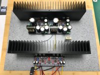
P.S.: A picture of DCG3 and SSLV1.3 (with additional input filtering)
It is interesting to me how transistors were 'working' that way - I would have never thought it's possible. Now I can finish my DCG3. 🙂
Just one more question: will single pair of SSLV1.3 be enough to supply both channels of DCG3 or would you suggest to build one for each channel?
Thank you very much for your help and paciance!
P.S.: A picture of DCG3 and SSLV1.3 (with additional input filtering)
Attachments
Although the shared SSLV is perfectly capable to support the preamp with very good results, dual mono PSUs will allow it to sound better still (mainly wider). If you have the box space.
Takes not only more space but yet another dual independent secondaries transformer and higher total shunt PSUs dissipation nonetheless.
Although you would notch down the CC current burden per reg in dual mono, the minimum spare current dissipation remains the same and multiplies heat by the more reg units.
Although you would notch down the CC current burden per reg in dual mono, the minimum spare current dissipation remains the same and multiplies heat by the more reg units.
Hi,
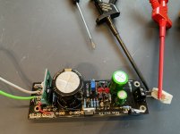
I have build 2 ultrabib positive regulators and cannot get them to run.
I attched a toroid transformer with 30vac output and used a saligny mosfet rectifier. R1 is below the pcb.
On both regulators I get 3,45v output and cannot set the voltage.
Did I make an obvious mistake?
Hope you can help.
Kind regards,
Attachments
- Home
- Amplifiers
- Power Supplies
- Salas SSLV1.3 UltraBiB shunt regulator