Hi Andy,
will look through my files tonight for the link to the switch. If I remember correctly, it was something from Conrad or Voelkner, so should be available in Norway as well.
Also, on the topic of P2P PSUs, I will dig out a few pictures tonight 😉
Regards, Claas
will look through my files tonight for the link to the switch. If I remember correctly, it was something from Conrad or Voelkner, so should be available in Norway as well.
Also, on the topic of P2P PSUs, I will dig out a few pictures tonight 😉
Regards, Claas
. KISS should be my slogan, got burnt many times allready complicating things.
This one of the most difficult challenges [emoji56]
I use the toroidy audio grade too. I just tap a M8 thread into the resin, deep enough that the torque is good without compromising the material. Thus 0% risk of having a closed loop = safe…
Yea, the holes are narrow. Managet to find a few M6s in the last house owners big box of nuts and bolts, so I am covered there.
How is your WLS coming along? My new boards arrived yesterday. 4 JFETs in.
Regards,
Andy
How is your WLS coming along? My new boards arrived yesterday. 4 JFETs in.
Regards,
Andy
Very good pictures of a nice build, Claas!
And good tips here with tapping the resin of the transformer.
And good tips here with tapping the resin of the transformer.
Regarding the NTCs for inrush current duty:
The CL-60s are tough, but as everything they have their limit. And everybody has to decide how much risk he can see with failing electric devices he himself build (risk for the people close to you, risk of fire, the insurance, ...)
In the old CL-60 datasheet, and also the new, I can't find the data for the maximum recommended energy rating in Joule. We know that many Pass amps use it (the bigger ones don't), and many diyers use it, too.
The energy the thermistors have to withstand can be calculated this way:
E = 0.5 * C * V².
I would have a look at other datasheets, compare the diameter, thickness and resistance, add a safety margin, and decide what my CL-60s will take for years.
If I had a bigger power supply (I have), then I would look for something different. A big guy for example is Amtherm's MS32 50006-L. It can take repeatedly 250 Joules.
Just a short anecdote:
When I switched on my amp after a moving, I saw some magic dust. 😱 What I found was very unlikely, because of 3 CL-60 thermistors (and of cause a complete F4) the CL-60 broke which was used as the ground breaker between the audio ground and chassis ground. After replacing it, the amp works completely normal. So, even if this CL-60 was WAY overspecced for this duty (as per schematic of Firstwatt Amps), it is normal that everything can fail in reality, if (ab)used or not.
This might be of interest:Regarding the NTCs for inrush current duty:
The CL-60s are tough, but as everything they have their limit.
Not thrilled with CL-60 inrush limiter in USA/160W Class A First Watt designs
How is your WLS coming along? . 4 JFETs in.
Veeery slowly.
Taking care of what was done the sloppy way, approaching significant steps (reconnect, test, etc.)
New back-plate:

[emoji39]
Hi Andy,
here we go:
regarding the front panel switch, it was from Conrad. I like to switch both phases, because, as we just had the discussion in the F4 thread, in a lot of countries in Europe you just don't know which phase ends up "live" and which "neutral" ...
Also, this one is with a 12V LED, but I just put a dropping resistor into my power tap from the 24V rail ...
TRU COMPONENTS LAS1-AGQ-22ZD, RD Tamper-proof pushbutton 250 V AC 5 A 2 x On/On IP67 latch 1 pc(s) | Conrad.com
Interestingly, on the German web site (conrad.de) it is listed about 10% lower in price ...
Regards, Claas
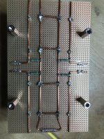
And here are some pictures of my PSU construction. It is not truly "p2p", because I built it on perf board (fibreglass, not resin paper, because of the heavy caps).
I first did the layout for the caps, the connectors for the chokes, and the wire attachment points, and drilled holes for the snap-in cap terminals, etc.
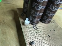
Connections underneath are done via pieces of 2.5 mm^2 solid copper wire (from house installation cable; about 13 AWG). The caps are secured by the solderjoints on the underside; when I'm finished I also like to secure the caps from above with hot melt glue in between them, but that's mostly for vibration damping.
Small trick: In one of the pictures you can see a piece of tissue wrapped around one of the spades. I often had the issue that when soldering spades from the underside, solder would wick up the spade and spoil the blade ... just wrapping some tissue around before soldering prevents this.
And finally, some bypass film caps for superstition ... 😀
I used spades / quick disconnects for the chokes. Raw DC wires from the rectifiers are soldered in, because these get disconnects at the rectifier bridges.The same goes for the rails - soldered in at the PSU board, because those get their disconnects at the motor run caps.
For power wiring I use also 2.5 mm^2 (13 AWG), but stranded wire, taken from a heavy-duty, but flexible mains extension cable (the one I like to use is from an outdoor cable). That's why in my amp builds you always see the quite boring color scheme of brown for plus, blue for minus, and yellow/green for ground ... 😛
Regards, Claas
I first did the layout for the caps, the connectors for the chokes, and the wire attachment points, and drilled holes for the snap-in cap terminals, etc.
Connections underneath are done via pieces of 2.5 mm^2 solid copper wire (from house installation cable; about 13 AWG). The caps are secured by the solderjoints on the underside; when I'm finished I also like to secure the caps from above with hot melt glue in between them, but that's mostly for vibration damping.
Small trick: In one of the pictures you can see a piece of tissue wrapped around one of the spades. I often had the issue that when soldering spades from the underside, solder would wick up the spade and spoil the blade ... just wrapping some tissue around before soldering prevents this.
And finally, some bypass film caps for superstition ... 😀
I used spades / quick disconnects for the chokes. Raw DC wires from the rectifiers are soldered in, because these get disconnects at the rectifier bridges.The same goes for the rails - soldered in at the PSU board, because those get their disconnects at the motor run caps.
For power wiring I use also 2.5 mm^2 (13 AWG), but stranded wire, taken from a heavy-duty, but flexible mains extension cable (the one I like to use is from an outdoor cable). That's why in my amp builds you always see the quite boring color scheme of brown for plus, blue for minus, and yellow/green for ground ... 😛
Regards, Claas
Attachments
Last edited:
Veeery slowly.
Taking care of what was done the sloppy way, approaching significant steps (reconnect, test, etc.)
New back-plate:View attachment 950721
[emoji39]
Got rid of the noise?
Long and busy day, Chede and Murdoc. But thanks a lot for very valuable - and impressive - contributions. I will take time tomorrow and answer fully. Thank you all for engaging in the thread, it really feels fantastic. Is say again: what a community!
Wish you all a good night!
Andy
Wish you all a good night!
Andy
And here are some pictures of my PSU construction. It is not truly "p2p", because I built it on perf board (fibreglass, not resin paper, because of the heavy caps).
I first did the layout for the caps, the connectors for the chokes, and the wire attachment points, and drilled holes for the snap-in cap terminals, etc.
Connections underneath are done via pieces of 2.5 mm^2 solid copper wire (from house installation cable; about 13 AWG). The caps are secured by the solderjoints on the underside; when I'm finished I also like to secure the caps from above with hot melt glue in between them, but that's mostly for vibration damping.
Small trick: In one of the pictures you can see a piece of tissue wrapped around one of the spades. I often had the issue that when soldering spades from the underside, solder would wick up the spade and spoil the blade ... just wrapping some tissue around before soldering prevents this.
And finally, some bypass film caps for superstition ... 😀
I used spades / quick disconnects for the chokes. Raw DC wires from the rectifiers are soldered in, because these get disconnects at the rectifier bridges.The same goes for the rails - soldered in at the PSU board, because those get their disconnects at the motor run caps.
For power wiring I use also 2.5 mm^2 (13 AWG), but stranded wire, taken from a heavy-duty, but flexible mains extension cable (the one I like to use is from an outdoor cable). That's why in my amp builds you always see the quite boring color scheme of brown for plus, blue for minus, and yellow/green for ground ... 😛
Regards, Claas
Chede, your PSU looks absolutely completely utterly fugly!
A couple of your design choices I want to ask you about, just for enlightenment.
1: I have chosen to decouple only the last set of caps before the amp boards, meaning the 100kuF’s. What was the reason you chose to decouple them all? Should I too?
2: You have made ground links across all caps. I am planning to only make one link, between the last set of caps. I am planning of cutting an aluminium triangle there, you know, 1980’s Krell+Choky style. This choice is a result of some discussion and reading this winter, with amongst others Bonsai. But I am open to try different things.
Other than that, I have many of the same things planned as in your PSU, including the gnd loop breakers.
Really cool of you to share!!
PS: lack of progress in my «rebuild», and lack of msgs in this thread, is due to new WLS boards arriving, so my time is spent getting that thing to work nowadays =)
Regards,
Andy
Last edited:
I'm also thinking about CL60 capacity and soft start circuit...
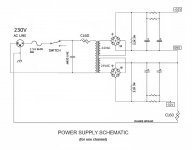
I'm starting to build a BA-3 (complementary bias) dual mono (one chassis),
with two 600VA 2x24V transformers and two CRC filters C=0,56F each channel ~1.12 Farad total.
I am aware this is absolutly oversized and not necessary but I quite like oversize PSU.
I am concerned about CL60, can I still use this circuit (avoiding fire)?
Attachments
Last edited:
I was wondering if I might risk to break the CL60, upon the switch on, due to the big capacitance ~1.2F
naah
point is having appropriate fuse ( not bigger than needed for declared VA of xformer) with chosen soft-start solution
if simple CL60 doesn't work, you can always change to chain of NTCs, switched across with relay after some delay
point is having appropriate fuse ( not bigger than needed for declared VA of xformer) with chosen soft-start solution
if simple CL60 doesn't work, you can always change to chain of NTCs, switched across with relay after some delay
A couple of your design choices I want to ask you about, just for enlightenment.
1: I have chosen to decouple only the last set of caps before the amp boards, meaning the 100kuF’s. What was the reason you chose to decouple them all? Should I too?
2: You have made ground links across all caps. I am planning to only make one link, between the last set of caps. I am planning of cutting an aluminium triangle there, you know, 1980’s Krell+Choky style. This choice is a result of some discussion and reading this winter, with amongst others Bonsai. But I am open to try different things.
Hi Andy,
To question 2:
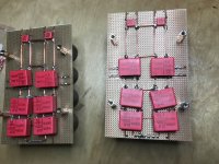
I built these PSUs two years ago for my SissySIT. That was before the discussion became widespread about connecting the grounds of the two rails only in one spot, on the clean side of the PSU. So I didn't take that into account and wanted only to make a ground connection as solid as I could, so I used multiple connections. The "clean" side is where you can see the "U", where I bent the ground wire around uninterrupted.
I have used this double-mono PSU now with two different amps - SissySIT and F4 with higher bias current. Both are absolutely silent over my 100 dB/W Jericho Horns - absolutely nothing, the most silent amps I have built so far. 😎
So in my case, having more than one connection between the grounds of the positive and negative rail hasn't hurt, it seems. 😛
To question 1:
I already called the additional film caps "superstition" in my original post 😉.
I just had the WIMAs lying around and needed to make use of the real estate on the bottom of the board, so I put as many in as would fit in convenient spots. If bypassing would bring real benefits, it should benefit also if bypassing caps earlier in the chain, or not ? 😉 Aah, and then there are the four Motor Run caps between PSUs and amp boards ...

At the input to the PSU from the diode bridges, I put a small film cap across. This is meant to be helping to quiet switching noise, if the diode bridges would have that ... probably more effective if attached directly at the pins of the bridge - somewhere around here I have seen a small PCB exactly for that.
Regards, Claas
Chede: thanks for that! There are obviously several alternatives. Since I won’t be soldering the PSU connections between caps, I have the opportunity to experiment a bit. Perhaps I will!
In other news, my WLS is up and running. Quiet and lovely.
That means refocusing on the BA-3 is in order. But I will do this slowly, since the amp is up and running.
I managed to get hold of two matched pairs of Toshiba NOS K170’s and J74’s @ 10mA, perfect for the front end. They will bias higher than my lower IDSS loafing LS JFETs, which according to Mr. Hui has an effect on what is served to the FE MOSFETs, so kinda excited about that. That means the FE will be to Papa’s spec.
I also secured quad matched NOS J74’s @ 6.8mA for the ACP+, so quite the happy camper.
Regards,
Andy
Last edited:
- Home
- Amplifiers
- Pass Labs
- BA-3 revisited