Then you will have 4 impulses so to speak. The normal sound, the diffracted sound, the direct correction signal and the diffracted correction signal. 2 of them may cancel on one axis but the four can spread elsewhere into the room, and return to the listening position.apply perfect DSP by convolving the midrange's driver input signal with an impulse corresponding to the inversed amplitude of the black curve. This would eliminate
This may also alter the tonal balance.
The (only) assumption is related to the psychoacoustic decoding of a (any!) two-peaked impulse into a (virtual and ambiguous) perception of azimutal informations. I have searched for studies about this, but didn't find anything in the literature so far in order to verify or falsify this assumption. I would very much like to know wheter this is plain BS or not.
If this assumption would be true, then this would establish a relation between the direct signal from the center of the driver and the delayed signal from the baffle diffraction on one side, and the potential blurring of azimutal perception on the other side: T_center_driver_to_baffle_edge would get a similar meaning as the TID by the specific psychoacoustic processing.
Yes. And I don’t see much contradiction in what you write later on. I agree on most of it.
But I do not quite understand this story about Geddes and “spaciousness” and “imaging”. Geometrically, I understand an “image” as one specific 2D representation of “space” (3D in these terms)? So “space” would be “image” plus the dimension of “depth” along with the psychoacoustic interpretation of ths perceived "soundfield"? Oh my, these terms ... isn't "field" 2D again ... And again much psychoacoustic processing we still do not unterstand well. Diving into the scull, we unfortunately do not have any longer these precise models as we have for the acoustic world outside the scull.
Anyway, maybe I should have better written “ … DSP can do practically everything, even if it can be used as a successful but exclusive “brute force” measure to compensate or minimize problematic diffraction behavior, at least for one point within the auditorium.” And I think it is quite evident from my writing that I strongly advocate the correct physical design of baffles in order to smooth the diffraction effects. Before applying any DSP in order to correct for an eventually misbehaving diffraction. By the way, I also opt for aerodynamics before motor power, but certainly do appreciate and welcome both options.
Nice investigative work. Well written and well explained. Thanks.
Regarding DSP, I understood you to be primarily talking about what DSP can accomplish with regard to diffraction,.... and i agree with your conclusions.
The issue of 2D vs 3D soundfield seems to me to have little to do with DSP (or diffraction), and mainly to do with a speaker's acoustic radiation pattern.
I do think diffraction can be corrected via impulse inversion techniques like you presented that address time domain issues for more than one point in space.
I make such corrections rather meticulously, either directly on-axis or sometimes slightly off-axis, and then rotate the speaker to measure how well the corrections hold up.
Minimum-phase magnitude corrections can be made with or without additional time domain (phase) corrections.
When on-axis phase is also corrected, I've found rotations to hold up better than mag only corrections.
I attribute/assume the phase corrections have to be addressing diffraction as well as direct driver response.
Summed drivers work better too, under rotation, when the phase of each has been individually corrected on-ax prior to summation..
Thank you for that very evident counterargument. It makes much sense!... I think we must not underestimate the power of masking. Recognizing a second, almost identical signal, weaker than the first and several hundreds of microseconds later is highly problematic for us. ...
Then you will have 4 impulses so to speak. The normal sound, the diffracted sound, the direct correction signal and the diffracted correction signal. 2 of them may cancel on one axis but the four can spread elsewhere into the room, and return to the listening position.
This may also alter the tonal balance.
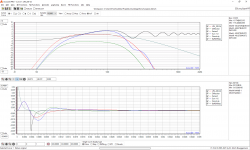
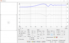
Four pictures to sequentially show what happens performing the filtering/convolution (e.g. of a baffle step):
1_Initial
Shows everyting "native" and as before with ...
Red: The ideal bandpass (LR4 200Hz ... 2kHz)
Green: The modeled diffraction
Blue: The total response as the summed impulse of bandpass and diffraction
Grey: The driver's polar behavior
Black: The difference between the ideal bandpass and the total response, aka the so called "baffle step"
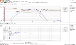
2_AmplitudeInversion
Now generate a filter with the inverse of what is to be corrected:
Black: The baffle step artefact
Brown: The inversed amplitude of this. This is the filter for the convolution.
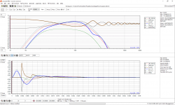
3_Convolution
Blue: The system's response as before, to be convolved with
Brown: The filter as synthesized before
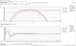
4_Result
Grey: The result of the convolution process. The curve has been raised by +2dB to separate it from the ideal response we started from.
Red: The ideal bandpass response.
Look at the red (ideal bandpass) and the grey (result of the convolution) data points in the time domain and at the frequency range. They are strictly identical besides the artificial +2dB raise of the convolved result. Where would you expect impulses from impulses from impulses then ... and where would you expect alterations of the tonal balance?
I would say that world's best midrange is the one with a successfully performed overall correction. It has been mentionned before: A nice frequency behavior is king. Because it also comes along with a nice impulse in the time domain.
Attachments
Indeed it's not a simple subject - and I apoligize for making it unnecessary worse by pulling in a story about Geedes' preference towards imaging. I think I had a point... but maybe it's too far out for this thread 😱Yes. And I don’t see much contradiction in what you write later on. I agree on most of it.
But I do not quite understand this story about Geddes and “spaciousness” and “imaging”. Geometrically, I understand an “image” as one specific 2D representation of “space” (3D in these terms)? So “space” would be “image” plus the dimension of “depth” along with the psychoacoustic interpretation of ths perceived "soundfield"? Oh my, these terms ... isn't "field" 2D again ... And again much psychoacoustic processing we still do not unterstand well. Diving into the scull, we unfortunately do not have any longer these precise models as we have for the acoustic world outside the scull.
Anyway, maybe I should have better written “ … DSP can do practically everything, even if it can be used as a successful but exclusive “brute force” measure to compensate or minimize problematic diffraction behavior, at least for one point within the auditorium.” And I think it is quite evident from my writing that I strongly advocate the correct physical design of baffles in order to smooth the diffraction effects. Before applying any DSP in order to correct for an eventually misbehaving diffraction. By the way, I also opt for aerodynamics before motor power, but certainly do appreciate and welcome both options.
But I still can't grasp how you can fix diffraction with a DSP - since a change in the signal to the driver, will change at every other angle too 😕
Take II - Addendum to previous post - sorry, it was too late to edit
You may see a cyclic behavior of the (brown) correction filter in graph 3, e.g. in the inverse of the baffle step. This might be the location of the impulse of the impulses of the impulse's successions you were expecting. So, in the filter used for convolution, it is the correction of the correction of the correction of the correction, so to say. And the result stays clean. Very clean.
And then another variant, a hopfefully more acourate answer to your question about the altered tonal balance: It is not "Not" as I stated before. It is a big YES, insted. A YES, of course! You will certainly alter the tonal balance towards more neutrality, e.g. towards less acoustic signature of the speaker.
Then you will have 4 impulses so to speak. The normal sound, the diffracted sound, the direct correction signal and the diffracted correction signal. 2 of them may cancel on one axis but the four can spread elsewhere into the room, and return to the listening position.
This may also alter the tonal balance.
You may see a cyclic behavior of the (brown) correction filter in graph 3, e.g. in the inverse of the baffle step. This might be the location of the impulse of the impulses of the impulse's successions you were expecting. So, in the filter used for convolution, it is the correction of the correction of the correction of the correction, so to say. And the result stays clean. Very clean.
And then another variant, a hopfefully more acourate answer to your question about the altered tonal balance: It is not "Not" as I stated before. It is a big YES, insted. A YES, of course! You will certainly alter the tonal balance towards more neutrality, e.g. towards less acoustic signature of the speaker.
Hi, it is very difficult for me to understand (intuitively) how an EQ would change behavior of acoustic domain in more than one axis (or spot in case of diffraction correction). One can correct perfectly where the mic is measuring, but the correction makes all other angles worse since the issue is in acoustic domain and in 3D and the effect (of diffraction) happens different time than the direct signal from the speaker.
I mean the EQ affects the driver power response whereas the diffraction is zero sum game in regarding to the speaker power response. The driver might have flat power response and it is the diffraction that makes these varying interference patterns to various directions. The driver frequency and impulse response could be perfect until the diffraction comes in and ruins it (after the driver has done its job as well as it possibly can). Or the driver response could be anything else than perfect and still the diffraction adds precisely the same effect as before. The diffraction doesn't mind what the signal from the driver is and what the driver is.
If I think about that a convolution (counter acting in time domain?) somehow the issues I don't think it can because the diffraction at baffle edge and the driver emits the sound at different time. I mean the driver would have to emit a "counter smear" for the diffraction to cancel out, but this only affects one location in space and everywhere else the response gets even weirder.
I admit I don't fully understand the FIR and convolution and stuff but surely it doesn't control the baffle edge, only the driver output.
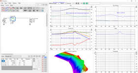
Attached is an example, I'm not sure if I'm doing it right but it is a VituixCad diffraction simulation ~3" driver at 44cm rectangular baffle. With and without a single parametric EQ filter demonstrating what happens if you correct a diffraction dip (or peak). Makes the situation a lot worse. I don't know how to do a convolution, but I believe it is possible to simulate in VituixCAD if somebody wants to try. Attachment contains the vituixcad project and frequency response files from the diffraction simulator.
I mean the EQ affects the driver power response whereas the diffraction is zero sum game in regarding to the speaker power response. The driver might have flat power response and it is the diffraction that makes these varying interference patterns to various directions. The driver frequency and impulse response could be perfect until the diffraction comes in and ruins it (after the driver has done its job as well as it possibly can). Or the driver response could be anything else than perfect and still the diffraction adds precisely the same effect as before. The diffraction doesn't mind what the signal from the driver is and what the driver is.
If I think about that a convolution (counter acting in time domain?) somehow the issues I don't think it can because the diffraction at baffle edge and the driver emits the sound at different time. I mean the driver would have to emit a "counter smear" for the diffraction to cancel out, but this only affects one location in space and everywhere else the response gets even weirder.
I admit I don't fully understand the FIR and convolution and stuff but surely it doesn't control the baffle edge, only the driver output.
Attached is an example, I'm not sure if I'm doing it right but it is a VituixCad diffraction simulation ~3" driver at 44cm rectangular baffle. With and without a single parametric EQ filter demonstrating what happens if you correct a diffraction dip (or peak). Makes the situation a lot worse. I don't know how to do a convolution, but I believe it is possible to simulate in VituixCAD if somebody wants to try. Attachment contains the vituixcad project and frequency response files from the diffraction simulator.
Attachments

Last edited:
I find this discussion super interesting. Maybe it should be spun off in its entirety into a new thread? Because a) it deserves it and b) it would thereby escape the original thread's clickbaitish title (and karma).
The discussion seems to evolve into the direction of "best practice for DSP speaker correction".
So then.
Convolution with the speaker's inverted SPL response as the filter will provide a perfect result for the xyz point of space from where this initial SPL response has been measured. As mentionned mutiple times before, at only one and this point, strictly speaking. So forget convolution because of this? No. You have to compromise (once again ...) for a best possible result. In order to not do make things worse within this optimized hearing zone. But better.
Convolution's result and quality will be determined by the filter(s) quality and the experience of their's builder: It's your decision if you generate the filter(s) from a single measurement or a set of measurements which then you average. It's your decision if you measure at 5cm from the driver (excluding the baffle diffraction) or at 1m (including it). It's your decision wheter you window out the room response (by only using the part of the impulse response before any room artefact occurs, usually the floor reflection), or if you include part of the room response or all of it (which usually isn't such a good idea).
What has been shown by now with the graphs I posted is "only" a single model use of convolution which feeds the driver with a specific signal counteracting the modelled baffle diffraction. That's all.
In a real-world multiway system you would filter/convolve all of the single ways to perform nicely in terms of theirs target SPL response and in terms of theirs target relative phase. And then you would apply another convolution over the whole system. And you would have to, well knowing the limits, compromise on all of these filters.
If you are interested to make your own experiences, have a look at Henrik Enquist's CamillaDSP as DSP engine. It's modern, free, fast, well written, and has an own thread here on the forum. For filter's generation I use Uli Brüggemann's Acourate. For most average DIYer Acourate may be overkill in terms of features. But it's a very nice, intuitive (proprietary) windows application and it's worth at least 🙂 twice the sum it costs. There is a free demo version.
DSP/convolution is not the allround magic wand of speaker builders, but it is a very powerful tool. And as with every powerful tool, when not well applyied, you may distroy the whole world. So use it well and decently.
Last edited:
@tmuikku, I find your example illustrative. The blue curve, speaker power in the second attachment (second graph.. middle left) shows that before specifically doing anything about the diffraction, it averages out to be fairly smooth. EQ would change this.
One way you could generalise it may be that all energy gets to the edge and diffracts, it doesn't necessarily get frequency specific due to that unless you stand in one spot and experience the comb filtering, and therefore there may be diffracted energy present even when it doesn't show up on a response plot. So if you do try to correct the response variations you are doing a kind of symptomatic treatment.
All this even before considering the room.
It has been demonstrated that you don't only hear the response of diffracted energy, but the timing and the angle it comes from, (not talking directivity, but meaning that it can sound like it comes from the direction of the edge of the speaker so you can hear a silouhette of the box).
Yes, and when you recognise this is happening, if you can tell that you can partially EQ an issue but EQing it all the way creates (or leaves) a problem then you know that the correct action (as you also allude to) would be to undo the EQ, fix the acoustic problem, re-measure and start again.Daihedz said:You will certainly alter the tonal balance towards more neutrality
Do you think 'shocking' should be decapitalised?clickbaitish title
I hope the last two posts were a joke! But anyway, here I go...
Just because it does not suit your opinion, thread should be terminated? Key word is "opinion" here, Thread starter made a real world effort with statistics and is bashed for that? Why don't you stick to facebook instead? ;o)
Just because it does not suit your opinion, thread should be terminated? Key word is "opinion" here, Thread starter made a real world effort with statistics and is bashed for that? Why don't you stick to facebook instead? ;o)
(off-topic)
Regarding the thread title.
I'm not trying to make a determination here, but look at this as an administrative duty only. I'm quite happy to restore the original title, or have another mod look at the issue, or have a short discussion here which can be removed when the issue is resolved, or we can start a 'poll' style thread and vote on alternatives. This is your thread.
That said, I decapitalise thread titles on a regular basis so please understand if I didn't think much of it.
[Off-topic]
I understand that such things can happen as a in an inconsiderate routine.
But while decapitalizing is ok, to change a titel's meaning is not. It is the kind of control and interventions that makes me leave a forum. Because of it's autocratic smell. Furthermore it has flawed my own routine to search for this thread by using the term "shocking".
So plese re-consider to re-fit the term "shicking" as a decapitalized item.
[End off-topic]
Last edited:
Allen, the last 40 or so posts are (off-topic😉
What is your take on the result here? I have done it myself with Seas paper and Visaton alu driver, 60% success is not good...
Edit: I misunderstood termination, but changing title without consent with thread starter is not ok as long it is not misleading or offensive
What is your take on the result here? I have done it myself with Seas paper and Visaton alu driver, 60% success is not good...
Edit: I misunderstood termination, but changing title without consent with thread starter is not ok as long it is not misleading or offensive
Last edited:
It is done.So plese re-consider to re-fit the term "sh[o]cking" as a decapitalized item.
My take on which result? Can you point back to it please.peterbrorsson said:What is your take on the result here? I have done it myself with Seas paper and Visaton alu driver, 60% success is not good...
Well, I don't remember which drivers JonBocani tested with, but it was two totally different drivers in size.
I tested if I could hear difference of a Seas 6.5 inch and Visaton AL170. Paper vs aluminium, similar driver size, same box, both crossed 1.8kHz, similar equalised, with tweeter and without. To be honest, I could not hear any difference even when it was un-blinded (is that a word🙂
I tested if I could hear difference of a Seas 6.5 inch and Visaton AL170. Paper vs aluminium, similar driver size, same box, both crossed 1.8kHz, similar equalised, with tweeter and without. To be honest, I could not hear any difference even when it was un-blinded (is that a word🙂
Why not eliminate it entirely?
I only meant the word "SHOCKING", not the thread. It is a very interesting discussion lately.
- Home
- Loudspeakers
- Multi-Way
- World's Best Midranges - Shocking Results & Conclusions.