I think if I am going to make modifications I would take the "full route" and implement two SMPS filter boards and drill two extra holes for Neutrik SpeakOn connectors I would use for power and then run it with two SMPS bricks for "true" dual mono.
First I run it "as is" and will check for crosstalk.....
First I run it "as is" and will check for crosstalk.....
X, you used yellow/green wires for safety earth connection. Can you confirm that the chassis IS safety earth via the MeanWell brick?
There was some debate as to whether the brick output is isolated from earth or not. I cannot check mine, as I still have not received my parts kit.
There was some debate as to whether the brick output is isolated from earth or not. I cannot check mine, as I still have not received my parts kit.
Hi Mbrennwa,
The Mean Well jack has 2 pins for 0v and 2 pins for positive 36v and 2 pins for shield or earth ground. I confirmed that the earth ground on the mains IEC plug is connected to the 0v internally at the SMPS brick.
If you look carefully at the bundle of wires from the 4pin jack, you will see 4 wires coming out of the braided cover: 2red, 2black, and 2green.
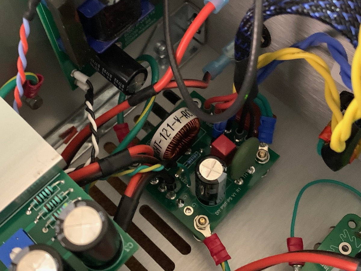
At the inside of the 4pin DIN connector for the Mean Well are 6 pins total. I have two wires on the outside which I assume are the shield/earth ground and they are connected to the 0v pins. I have the two shield earth wires going to the chassis via crimp loop connectors. The reason I bond the heatsinks to the chassis is to prevent the reliance on the screws that hold the heatsink and bottom panel together to form a good chassis ground. Grounding the heatsink usually makes the amp quieter. Not that this amp is noisy. It’s silent.
The Mean Well jack has 2 pins for 0v and 2 pins for positive 36v and 2 pins for shield or earth ground. I confirmed that the earth ground on the mains IEC plug is connected to the 0v internally at the SMPS brick.
If you look carefully at the bundle of wires from the 4pin jack, you will see 4 wires coming out of the braided cover: 2red, 2black, and 2green.
At the inside of the 4pin DIN connector for the Mean Well are 6 pins total. I have two wires on the outside which I assume are the shield/earth ground and they are connected to the 0v pins. I have the two shield earth wires going to the chassis via crimp loop connectors. The reason I bond the heatsinks to the chassis is to prevent the reliance on the screws that hold the heatsink and bottom panel together to form a good chassis ground. Grounding the heatsink usually makes the amp quieter. Not that this amp is noisy. It’s silent.
Last edited:
I think if I am going to make modifications I would take the "full route" and implement two SMPS filter boards and drill two extra holes for Neutrik SpeakOn connectors I would use for power and then run it with two SMPS bricks for "true" dual mono.
First I run it "as is" and will check for crosstalk.....
Neutrik makes PowerCon connectors designed for robust, make/break under live load connectors for AC mains. You can use it for DC of course.
NAC3MPXXA | Neutrik

I asked that question to Neutrik if it was recommended for DC (a while ago) and I got this answer back from Neutrik. After that I purchased some of the SpeakOn connectors. Here is the answer I got from Neutrik:
"Thank you for your interest in Neutrik products.
I would not recommend to use the PowerCON for anything else than 230V applications as it is “sold as such” and you will run into the risk that someone “hooks it up to 230V” and you will have to “re-order”…..
Yes, all of our products are AC rated as we originally are a company that designs and produces for Audio applications. And audio is AC…..
However, that does not mean that our products cannot be used for DC but as our ‘Target Market” has hardly any interest in that we do not specify those (DC) properties.
I could recommend our Speakon line of products, made for higher currents and lower voltages (less risk when mixed up with other applications). They basically have the same form factor so that should fit you as well.
http://www.neutrik.com/en/speakon/
Please inform if you have additional questions,"
..the brick output is isolated from earth or not.
Brick output is not isolated from safety earth.
After my continuity test the safety earth pin is connected with V(-) two wires.
In 6L6 build guide you can see safety earth is soldered to SUPP(-) = G
source: Sony Vfet (P, 2021) - diyAudio Guides
on the psu filtering board then thermistor to the chassis with the screw
")
Edit: All chassis parts: Heatsinks, transistors aluminium T brackets, front panel etc.
tightened with the screws is automatically all connected to the safety earth with thermistor like on the original schematic.
In my understanding amplifier don't have inrush current at power on
first capacitors charge slowly..after that is start conduct current..
Correct ?
Attachments

You can add capacitance to the supply until the Meanwells won't start. Actually,
the Meanwells will pulse charge the caps up as long as the circuit itself doesn't
start to draw current, so you can play with the capacitor on the constant current source to delay that further if needed.

Large CCS capacitor = longer time current draw start delay = possibility to add more psu capacitance.
This is simple " soft start " correct ?Hi fellow builders,
I am happy to report that number 034 is now alive and singing. It is awesome!
I took my time with this build, and spent around 10-15 hours to complete. I really enjoyed the process, and I was determined to not make any mistakes.
After setting bias, I connected to my really-not-ideal diy 84dB 6 Ohms transmission line speakers. In that setting it sounds really relaxed, wide soundstage and just very pleasant to listen to. I fact, now my stereo sounds so relaxed and lush that I am starting to wonder if I've done something wrong with my F6. It sounds very different, and I prefer the Vfet by far. Anyone else had a chance to compare their vfet to an F6 (or and F5) and care to comment? I'd love to hear about other peoples experiences.
Slowly putting this amp together have made me feel very privileged and lucky to be a part of it. I build my first amp in 1988, a Lindsley Hood 10W class amp (2N3055 output devices) and have in between lived with a Pass A40, a few acas, and a F6. I don't think I will ever build anything as unique as the vfet. I love it already. Huge huge thanks to Nelson, Jason, Jim (awesome build guide!) and the rest of the community.
Jan.
It's a very easy amp to listen to. I agree about the relaxed sound description, and the extra soundstage width / depth is really nice. Allan Taylor's "Colour To The Moon" was sounding extremely pleasant last night, as an example. I remember my old single ended BA-1 having this sort of easy laid back presentation, yet still detailed. But the VFET adds more depth and layering I think. My BA-1 had double the power and more gain though. F4 probably better for rock / metal. I haven't done any comparison's... My F6 fell apart a little bit with complex music, maybe there was a problem with my build, not sure...
I feel that zero feedback Class A amps have the advantage of excellent imaging and soundstage compared to amps with negative feedback. The VFET is indeed easy to listen to. Very smooth and non fatiguing. I think it handles clipping very well too - soft and controlled from what I (don’t hear).
I noticed that XRK971 placed the input board close to the rear panel and centered the output board in the heatsink. I was tempted to do the same as theoretically this should result in better heat dissipation. I realize that in the future when new input boards are introduced they may not fit. I am very happy with the sound of the amp as is. Not wishing to alter a masterpiece I am thinking of moving the output board to the center of the heatsink. My question is , will the move have a significant impact on the temperature of the VFET and if so has any measured it?
The most important thing for getting good heat dissipation is to make sure the T brackets are mounted firmly to the heatsinks. Extra washers are necessary under the machine screw heads to make sure the screws don't bottom out in the mounting holes. A split ring lock washer plus the included flat washers is probably enough.
Aluminum conducts heat well enough that a shift of the OS modules one way or another makes little difference. Mounting the OS somewhat more forward will leave more room in the chassis for alternate FE cards, if you wish to try something different later on.
Aluminum conducts heat well enough that a shift of the OS modules one way or another makes little difference. Mounting the OS somewhat more forward will leave more room in the chassis for alternate FE cards, if you wish to try something different later on.
Thanks for answering my question. I will leave the OS modules in place as per the build guide and spend my time time enjoying the amp. I just can't get over how great this little amp sounds. Many thanks to Nelson Pass , Jim and everyone else involved in making this possible.
...I just can't get over how great this little amp sounds. Many thanks to Nelson Pass , Jim and everyone else involved in making this possible.
Agreed! My system has never sounded so good. This amp is spectacular. On all forms of music, too! Many thanks again.
It's a very easy amp to listen to. I agree about the relaxed sound description, and the extra soundstage width / depth is really nice. Allan Taylor's "Colour To The Moon" was sounding extremely pleasant last night, as an example. I remember my old single ended BA-1 having this sort of easy laid back presentation, yet still detailed. But the VFET adds more depth and layering I think. My BA-1 had double the power and more gain though. F4 probably better for rock / metal. I haven't done any comparison's... My F6 fell apart a little bit with complex music, maybe there was a problem with my build, not sure...
Thanks for your reply, William, and to the others as well.
What kind of speakers are you guys playing? I am curious how the vfet would work with audio note for instance. Or with something considerably more efficient than my current setup.
The most important thing for getting good heat dissipation is to make sure the T brackets are mounted firmly to the heatsinks. Extra washers are necessary under the machine screw heads to make sure the screws don't bottom out in the mounting holes. A split ring lock washer plus the included flat washers is probably enough.
Aluminum conducts heat well enough that a shift of the OS modules one way or another makes little difference. Mounting the OS somewhat more forward will leave more room in the chassis for alternate FE cards, if you wish to try something different later on.
I am having some doubts about the effectiveness of the TO3 heat conducting pads being used. Seems thick and more of a thermal insulator than a conductor to me. The VFET gets really hot really quick compared to the heatsink with little thermal inertia. I have not measured any temp yet but I don't have the specs for the pad either. Does anyone have the thermal conductivity specs for the pad? Is this better than classic grease-mica-grease?
- Home
- Amplifiers
- Pass Labs
- DIY Sony VFET Builders thread