Take voltage readings at various places on the good and bad channels, and post them here for comparison. Printing out schematic and putting the readings on there would be even better.
Thank you for advice, ZM.
But i have -4V offset when bias resistor reading is only 0,02V. I can increase offset, make it -5V, for example, but i can't make it close to zero when bias higher than 0.
I have biased other channel with no problem.
But i have -4V offset when bias resistor reading is only 0,02V. I can increase offset, make it -5V, for example, but i can't make it close to zero when bias higher than 0.
I have biased other channel with no problem.
something is wrong and you must find what is it
have 6V8 across zeners?
mosfets isolated from heatsink? ( small metal bur can ruin your day) - check that measuring resistance between heatsink metal and mid pin of mosfet
-recheck all resistors once more, including trimpots
-if measuring resistor in circuit is giving suspicious reading, unsolder one end from pcb
My F6 is alive! Output transistor was fried.
Now all is ok, and it plays its first track)
Bias is 1.1A.
Please, have a look at my twins) left to right: F4 with BA3 front end (waiting for JFETS), F6, F5. It is the coolest arithmetic i've ever learned))
Many thanks to all of you, to 6l6 for the build guide, to ZM for advices, and to Mr. Pass for his genius!
Try increasing the bias to 1.6 Amps or as much as 1.8 Amps. As long as the heat sinks can be touched for 10 seconds, you’re Ok.
Try increasing the bias to 1.6 Amps or as much as 1.8 Amps. As long as the heat sinks can be touched for 10 seconds, you’re Ok.
I have seen ( using QA401 ) that over 1.5 A , distortion is rising as much as the temperature , and for me the "sound " doesn't benefit , it may depends of the setup of each one
I personally stop and stay at 1.4 A , it seems to be the best sound/distortion ratio 😉
It also seems that some like it more "colored" , so why not 😉
.
Last edited:
My output Mosfets are FQH44N10, which sound better at higher bias. Maybe just the right amount of color.
My F6 is alive! Output transistor was fried.
Now all is ok, and it plays its first track)
Bias is 1.1A.
Please, have a look at my twins) left to right: F4 with BA3 front end (waiting for JFETS), F6, F5. It is the coolest arithmetic i've ever learned))
Many thanks to all of you, to 6l6 for the build guide, to ZM for advices, and to Mr. Pass for his genius!
View attachment 948941View attachment 948942View attachment 948943View attachment 948944View attachment 948945
Congrats. Those are makulu heatsinks! Enough for lots of heat.
Thanks for bias level advices.
I have Alepb J in the same case with bias 1.7A. heatsink temperature is 59ºC.
Now i set 1.1A just for test.
I have Fluke digital oscilloscope with FFT function. So, i will measure distortion soon and ajust bias.
I have Alepb J in the same case with bias 1.7A. heatsink temperature is 59ºC.
Now i set 1.1A just for test.
I have Fluke digital oscilloscope with FFT function. So, i will measure distortion soon and ajust bias.
I feel so sorry because of my stupidness.
I had silly mistake for wiring PSU rail +/- opposite
when changing reflector diode only few seconds.
There was no smoke but no sound come out.
3 Leds instead of zenner diode still lights on
But when I turn off, Z1 stay on for few seconds but Z2
Turn off quickly.
What is possibly damaged?
I had silly mistake for wiring PSU rail +/- opposite
when changing reflector diode only few seconds.
There was no smoke but no sound come out.
3 Leds instead of zenner diode still lights on
But when I turn off, Z1 stay on for few seconds but Z2
Turn off quickly.
What is possibly damaged?
Attachments
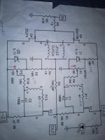
There is no voltage coming on transformer so probably
Temperature fuse on transformer brow up,also there must be another problem on pcb.
Temperature fuse on transformer brow up,also there must be another problem on pcb.
I feel so sorry because of my stupidness.
I had silly mistake for wiring PSU rail +/- opposite
when changing reflector diode only few seconds.
There was no smoke but no sound come out.
3 Leds instead of zenner diode still lights on
But when I turn off, Z1 stay on for few seconds but Z2
Turn off quickly.
What is possibly damaged?
Have a look at R1 and R2 , I made the same mistake years ago and those resistor were well burn and almost dead 😉
what you did is kinda short , so high current occur in the all power supply circuit , have a look at the all power supply
.
Fuse ratings
What fuses are being used in the AC/Fuse/Switch receptacle?
I am ready to start testing/adjusting and have some 5mm X 20mm 250V fuses but I do not know what rating of fuse to use in each of the two locations in the receptacles holder drawer.
Thank you
What fuses are being used in the AC/Fuse/Switch receptacle?
I am ready to start testing/adjusting and have some 5mm X 20mm 250V fuses but I do not know what rating of fuse to use in each of the two locations in the receptacles holder drawer.
Thank you
AudGuy,
For the hot line fuse and for the neutral fuse I believe 2.5A or 3A (Slow Blow) each will be fine for your F6, especially if you have implemented the CL-60 thermistor/softstart with the DIYAUDIO power supply board.
If you look on the 1st page of this thread, you'll see the power supply schematic and it has detailed the value of the fuse. Although it shows only a 2.5A slow blow in the hot line, having a 2.5A fuse in the neutral line is an additional safety measure and since your fuse holder accommodates it then why not.
Best,
Anand.
Last edited:
If both the hot and neutral wires are fused, for safety, the neutral fuse should be higher current capacity so that in the event of a fault, the hot fuse will blow. If the neutral blows instead, the hot line is still live and there is still electricity in the chassis.
If both the hot and neutral wires are fused, for safety, the neutral fuse should be higher current capacity so that in the event of a fault, the hot fuse will blow. If the neutral blows instead, the hot line is still live and there is still electricity in the chassis.
Ben,
Excellent point. So would you recommend a 3A in the neutral and 2.5A in the hot line?
Thanks,
Anand.
For the neutral fuse, I would choose one that is many amperes higher than the hot fuse. For the hot fuse, I usually take the transformer VA and divide it by the Line AC voltage to get the fuse size. For the neutral fuse, I would perhaps at least double the hot fuse capacity. Then it is of utmost importance to properly identify the hot fuse and neutral fuse locations and install the fuses in the right locations.
All my amplifiers have only a hot fuse so I have not had to deal with this situation.
All my amplifiers have only a hot fuse so I have not had to deal with this situation.
- Home
- Amplifiers
- Pass Labs
- F6 Illustrated Build Guide