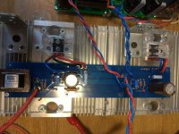
Oh, in another wonderful turn of events I managed to FUBAR a Toshiba 2SJ74BL last night.
Henry,
See here.
That's exactly what happened to tbrooke's build.
I do recommend a good variac for everyone. I slowly raise up the voltage, pause every 10-20 volts and watch for any mishaps to happen. It gives me additional insurance compared to a dim bulb tester which I have but hardly use.
It happens, and you learn!
Best,
Anand.
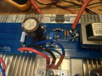
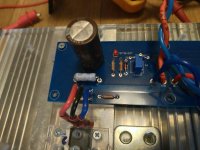
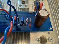
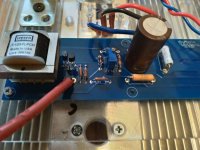
Referring to post 3458, I picked up a hum after arcing to my meter probe while setting the bias. Diode bridges are OK. The bias and offset work normally. Before unsoldering parts, I need an opinion. Could C1 have been damaged causing the hum? Regards, Bill Edit: I meant C2.
At this point, a picture or two might be useful for us to see. C2 or C1? Perhaps. That's assuming that all else in your build was good in the 1st place and you didn't have any cold solder joints that slowly lost conductivity since your initial fire up was a success.
All that being said, have you invested in mingrabber test clips yet? 😉 Slipped meter probes cause shorts all too often. This is good insurance:
Minigrabber(R) Test Clip With Pin Tip Jack, Availible In Black Or Red | Pomona Electronics
Best,
Anand.
Last edited:
Henry,
See here.
That's exactly what happened to tbrooke's build.
I do recommend a good variac for everyone. I slowly raise up the voltage, pause every 10-20 volts and watch for any mishaps to happen. It gives me additional insurance compared to a dim bulb tester which I have but hardly use.
It happens, and you learn!
Best,
Anand.
Actually, the desoldering screwed it up. Too much heat and pulled on the legs too hard I think. It was a dead short after the desoldering attempt.
It was one of the JFETs I got from Spencer that was the victim. I picked up the issue even before adding any power.
Ah! For JFET removal, I don’t desolder. Just snip the leads, remove JFET (with ESD wrap attached to my wrist and grounded), leaving 1mm above the pcb and then remove the remaining leads with flux, heat and tweezers.
Best,
Anand.
Best,
Anand.
Poseidonsvoice, Thank you for the advice. I do have good Fluke high voltage test leads but when I extended the clips I got the arc. You can see in the picture of Board A that the bias resistor is just below C2. I will check to see if the bias resistor is soldered properly. The amp did work fine before the arc. Regards, Bill
Attachments
Changes out C2. Also reflowed the bias resistor. Still have the low level hum. Switched the RCA's around on the OPPO to see if that was it. Nope. This is the time for a scope but I don't have one yet. Should I be able to see the the hum using my DMM? If so, what would be the best approach? Bill
Bill,
Is this a 60Hz hum or a 120Hz hum? Do you have an app for your phone that can check the spectra? I have one called 'Spectrum'.
You are using the Oppo BDP 105 direct to the F6, yes? So it would be highly unusual for the Oppo to be a source of the hum in all honesty. Did you check your interconnect and make sure the RCA center pin from one end is connected to the other and the RCA ground is connected from one end to the other? Do you have another CD player or source you can connect to the F6 to double check? I would make sure it's a viable source that is well designed from a "grounding" standpoint. Many diy projects and some commercial designs are not great tests for this and can lead to more confusion.
Next, is there hum without anything connected to the RCA input of the F6? Is there hum, if you were to disconnect the RCA's to the input of the F6 pcb, and connect/solder a small wire from the input (+) on the amp pcb to input (gnd) on the amp pcb? Is the hum on both channels or only 1 channel? Are the RCA's well isolated from the chassis? Disconnecting the wires attached from the RCA to the PCB, is the RCA signal tab and RCA ground tab isolated from the chassis?
You can check all these with a multimeter.
Are all the power supply caps well soldered and seated on the PCB? It is highly unusual for a power supply cap to fail and not look ugly on the PCB. It is common to have a cold solder joint on a power supply cap due to poor thermal capacity of the soldering iron, poor soldering technique, etc...Did you tug on the ground wires going from each amp PCB to the power supply PCB and make sure there is good continuity? Is the CL60 properly connected from the PS PCB to chassis ground? Is the chassis ground properly connected to the IEC ground tab? Is the CL60 thermistor functioning as a ground loop breaker as it should?
Poke around, there is something loose somewhere. Again, all of these can be checked with a multimeter.
Your build pic for others to examine and see:
https://www.diyaudio.com/forums/pass-labs/360807-ultimate-4u-500mm-chassis-123.html#post6612774
Are those Cardas RCA's and binding posts? Are you sure the body of the RCA isn't touching/shorting onto the chassis from within the hole? Check. Cardas RCA's require a good amount of heat and thermal capacity from your soldering iron or else cold solder joints result.
99% of the time, most problematic situations in new diy builds can be solved with a multimeter, although I admit, I love my Keysight oscilloscope!
Hope that helps,
Anand.
Last edited:
Ah! For JFET removal, I don’t desolder. Just snip the leads, remove JFET (with ESD wrap attached to my wrist and grounded), leaving 1mm above the pcb and then remove the remaining leads with flux, heat and tweezers.
Best,
Anand.
Yes, I learnt my lesson. Let's hope I pay school fees only once. 😱
Anand,
Thank you for the very detailed reply. I loaded a spectrum analyzer app and found the hum to be 120Hz.
Hum only on left channel after I caused the arc when setting bias.
Checked interconnect continuity and found center pin and ground good end to end.
Hum is louder with interconnect disconnected.
Chassis RCA is not shorted to chassis based on meter test.
Disconnected wires from chassis RCA to pcb. Hum still present.
Shorted + and - signal wires after removing them from chassis RCA. Hum still present.
Checked my solder connections to PS and pcb. All appear to be good and remain tight after tugging on them.
CL60 ground lift seems good.
The Chassis RCA's are Cardas. I used the 750F setting on my Weller iron to get the ground and center pin soldered correctly. They were tight.
The odd thing is that the hum started after the arc to my meter probe, but it could be coincidental.
Anand, thank you again for you help. Regards, Bill
Edit: noise on left channel speaker terminals (where hum is) is 260mv.
On right channel the noise is ~20mv.
On right channel the noise is ~20mv.
To my uneducated knowledge it sounds like you have elevated ripple on the one channel. I would look more to the PSU side of the chain for the problem.
Have you measured the AC voltages on the DC lines coming from the PSU to the amp PCB?
Have you measured the AC voltages on the DC lines coming from the PSU to the amp PCB?
henryve,
Thank you for your comment. Both channels have about 43mv riding on the + and - DC where it enters the pcb. Dang. Regards, Bill
Thank you for your comment. Both channels have about 43mv riding on the + and - DC where it enters the pcb. Dang. Regards, Bill
Anand and henryve,
Found that I have 0.0V across R10 on the side with the hum and 1.5V on the other board. Still able to set bias, but I must has fried R10. I'll change it and see what happens. Hopefully I have another one.
Edit: The power off resistance in circuit is 10K. Now sure where to go from here. Regards, Bill
Last edited:
Bill,
Looks like from your testing that the hum source is intrinsic to F6 and not extrinsic.
Make a copy of the schematic and then annotate systemically what voltages you are getting (relative to ground) for the various parts of the left channel (then upload here). It’s a simple circuit - we should able to see if it’s a passive part that’s failing or (more commonly) an active device like the JFETS. Be careful and take your time. Comparing to the other channel can be helpful.
Although 120Hz points more towards a PS filter issue, I think here your PS is okay given that ripple is equal (and reasonably low) for +/- voltages.
The last F6 I repaired, the JFETS were fried. It was obvious by visual inspection (the labelling on the JFETS were tarnished) and immediately obvious on my transistor tester.
Best,
Anand.
chassis - minimum internal dimensions for F6 build. Transformer recommendations
Waiting for my F6 diyaudiostore parts kit to arrive, and trying to plan a chassis.
What would be the minimum space required for a F6 build, width, depth, height?
Also, I have a Khozmo stereo shunt attenuator unused (the one with 90+ dale resistors), could I add it to my F6 build instead of using a preamp?
In terms of a 230V power transformer to use in this F6 and other possible builds, what is recommended, from budget choices to insane?
Apologies for the random questions (this is my first build, please be kind)
About the attenuator... it is precisely that: it will attenuate from 0dbs (at full "volume") to, depending on your model, to something like -60db.
So what is your plan? Put the attenuator after the line inputs? That would be the equivalent of using a "passive" pre with no gain, and impedances need to be studied, I think. Depending on your source, this should not be the best match.
I will leave others give more input, but I wouldn't venture into too much changes for a first build as the chances of debugging any issue decrease with each component added and if you go with a very highly customized build, chances of the community giving input decrease a bit.
I am a newby myself, and therefore try to stick to tried-and-tested solutions and only "innovate" on the areas I feel 100% comfortable changing.
Congrats on starting your first build!!!
Last edited:
Modushop 4U/300 being minimum you can count on
take that as ref. if using some other source for case
some sort of buffered attenuator is always better to use than unbuffered, but final choice is yours
xformer - FW is routinely using 300VA Donut for common PSU for both channels
I like to use one per channel, overkill is making me feeling smarter
FW is having 8x15mF caps in Cap Bank common for both channels
I like to use 4x33mF per channel, same reasons as above
Anand, Thank you for the help. I will be able to get results later this week after some other obligations
Regards, Bill
Regards, Bill
hello, friends. i'm now firing up my F6 and i have a problem with one channel.
i made a mistake and mixed up Q3 and Q4 in one channel and got -24V DC at the output.
i have replaced them with new ones, but the channel does not want to adjust bias and offset.
when bias is 0, offset DM reads 0 too. but when i turn bias pot down and increase bias, bias DM reads 0.1 maximum, but offset DM reads -24V DC, and i cant adjust it.
if i decrease bias to 0, offset DM slowly goes to 0.
i checked every resistor before soldering.
Zenners are 6.8V, R7,R8 are 3k3
Jfets are from the DIY store
- Home
- Amplifiers
- Pass Labs
- F6 Illustrated Build Guide
![20210501_114710[1].jpg](/community/data/attachments/879/879019-ff5d12e3185afffb375088c9c81858cd.jpg?hash=_10S4xha__)
![20210501_114842[1].jpg](/community/data/attachments/879/879038-67555acbc7aff99d84a63165d3e4c341.jpg?hash=Z1Vay8ev-Z)
