Maybe O-scope not required?
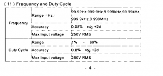
Maybe not! I just stumbled across the Aneng AN8002 multimeter which sells for USD 31.00 if you buy from Amazon or else USD 17.00 if you buy from Banggood. Its spec sheet includes the table attached below. 50 kHz and 36V pk-pk are definitely within its capabilities. I'll look to see if there are other, even cheaper DMMs that have similar specs, and buy the cheapest. Then we'll see whether an inexpensive DMM will or won't do an acceptable job on Marauder and Dreadnought.
_
... adjust trimmer potentiometer R25 ... I strongly recommend you use an oscilloscope and not a multimeter to perform the setting. You'll be measuring the frequency of a very high voltage AC swing. The AC voltage is too big for lots of meters' "frequency counter" mode, and the frequency is also too high.
Maybe not! I just stumbled across the Aneng AN8002 multimeter which sells for USD 31.00 if you buy from Amazon or else USD 17.00 if you buy from Banggood. Its spec sheet includes the table attached below. 50 kHz and 36V pk-pk are definitely within its capabilities. I'll look to see if there are other, even cheaper DMMs that have similar specs, and buy the cheapest. Then we'll see whether an inexpensive DMM will or won't do an acceptable job on Marauder and Dreadnought.
_
Attachments
Can't have too many meters! As a new customer they give you the option of either silicone nipple covers or $2.00 off. So if this meter works properly you can't beat a meter for $15.00! 😀
simple use the bare wire ,no connector at all or fly connector 😉I was not aware the PSU connector has 6 pins!

Seems like a Korg NuTube based input board would be the choice I might try. Not that I would have a clue how to do that, and don’t plan to beg here for one. With the 5 current choices for input cards, there will be much to build, and listen to this year. Group 3 (VFET-less kits) shipping is not planning to ship until this fall. I probably will look to build Mark’s WWII naval based set of input cards once I get confirmation about “winning” a Group 3 kit.
I’m also waiting to see if these cards are part of the new “SIT” amplifier cards expected to be out some day.
Thanks, some more, for putting in the work on these Mark.
I’m also waiting to see if these cards are part of the new “SIT” amplifier cards expected to be out some day.
Thanks, some more, for putting in the work on these Mark.
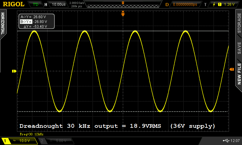
Here is Dreadnought operating juuuuuust before it clips. From a (+36V, GND) single ended supply, it's delivering 18.9V RMS at the Front End output. Which means Dreadnought has a comfortable safety margin beyond what the VFET output stage requires for full power ((3V * 5x) = 15V RMS at the VFET input). Click on the image to see it full sized and undistorted.
Or you could spin the picture data in a different direction: it means Dreadnought can drive other cards besides the VFET output stage. Cards which may not have been invented yet. Cards which may not have been announced yet. Cards whose operating principle may not be (follower + CCS load). Cards which operate from different power supplies. You get the idea.
Science types: although I believe it's correct, you can check my RMS arithmetic if you like. Start with delta-Y at top left.
_
Attachments

Last edited:
... Or you could spin the picture data in a different direction: it means Dreadnought can drive other cards besides the VFET output stage. Cards which may not have been invented yet. Cards which may not have been announced yet. Cards whose operating principle may not be (follower + CCS load). Cards which operate from different power supplies. You get the idea.
But I must ask before Zen Mod does... can it drive the F4?
😀
All joking aside, this is very pleasant news about the Dreadnought. I was considering just plain old stock, but now it may not be as simple as that with the Dreadnought.
If you've got a supercharged F4 with water cooled heatsinks, and if you run it from ±30V DC power supplies, then (Dreadnought) + (your goofy F4) + (8 ohm load) will give about 35 watts RMS per channel before clipping.
Standard F4s with normal heatsinks and normal power supplies, only go up to 25 watts per channel before clipping, according to the F4 documents on the First Watt website. Dreadnought easily drives those F4s to max output and beyond, without clipping at the input to F4.
On the other hand, now you've got to find a way to get (+36VDC, GND) to Dreadnought, a supply voltage which is not usually found inside an F4 chassis.
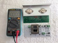
I bought the meter mentioned in post #103 above, it arrived today. Image attached, it's a small little booger.
Regrettably it did not correctly display the frequency of the Marauder card. It didn't even read a subharmonic or harmonic of the actual frequency. I tried direct coupling and AC coupling; wrong answer both times.
So it looks like you'll either need to use an oscilloscope to measure frequency, or else design and build a little buffer + attenuator on your solderless breadboard, which drops the peak-to-peak voltage swing to 9V or less, without loading down the Marauder circuit too much. Then a standard multimeter on frequency counter mode MAY be able to see it's 50 kHz. Unfortunately the best way to debug this little breadboarded circuit, is with an oscilloscope.
Sorry for the disappointing result. Glad I tried it, though.
_
Attachments
A diyAudio member has asked
I suspect it is too early to ask or answer this question. People are not yet familiar with Dreadnought, and VERY few people have studied both Dreadnought and MoFo. Certainly I have not -- although I do know Dreadnought, I haven't read any MoFo technical info at all.
I suspect that over time, this may change. Gradually, more and more MoFo experts will have the opportunity and the desire to study Dreadnought. Eventually there might be one or more of them who can answer your question.
However if anybody does have an opinion or an answer today, please reply today!
However, I was wondering if either of the Dreadnought or Bulwark cards could be used in the MoFo as a front end -- is it possible given the MoFo topology? It's hard to find a good voltage gain pre-amp to drive a MoFo (I know my B1 won't do it and haven't even attempted it). Would either of these cards be able to provide that extra push and lift in gain? Or not recommended.
I suspect it is too early to ask or answer this question. People are not yet familiar with Dreadnought, and VERY few people have studied both Dreadnought and MoFo. Certainly I have not -- although I do know Dreadnought, I haven't read any MoFo technical info at all.
I suspect that over time, this may change. Gradually, more and more MoFo experts will have the opportunity and the desire to study Dreadnought. Eventually there might be one or more of them who can answer your question.
However if anybody does have an opinion or an answer today, please reply today!
That is the multimeter I use for everything. It's the "best" thing I could find here... and it is your "trash" trial multimeter. LOL!I bought the meter mentioned in post #103 above, it arrived today. Image attached, it's a small little booger.
Ok. I was not hoping to measure frequencies, but at least I hope the voltage measurements and resistance are good enough! 🙂
I only tried it for measuring frequency on a weird waveform that no other meter seems to be guaranteed to read. This one is probably quite good otherwise and a screaming bargain for as many display digits as they offer. But it doesn't do the one thing I hoped it would.
Hah! Found the photo I was looking for. It's from my ACA build and dates from August 5th 2018! There you can see my Multimeter. It bears a different brand, but it's the exact same thing! This one-model-multiple-branding habit is a bit annoying.
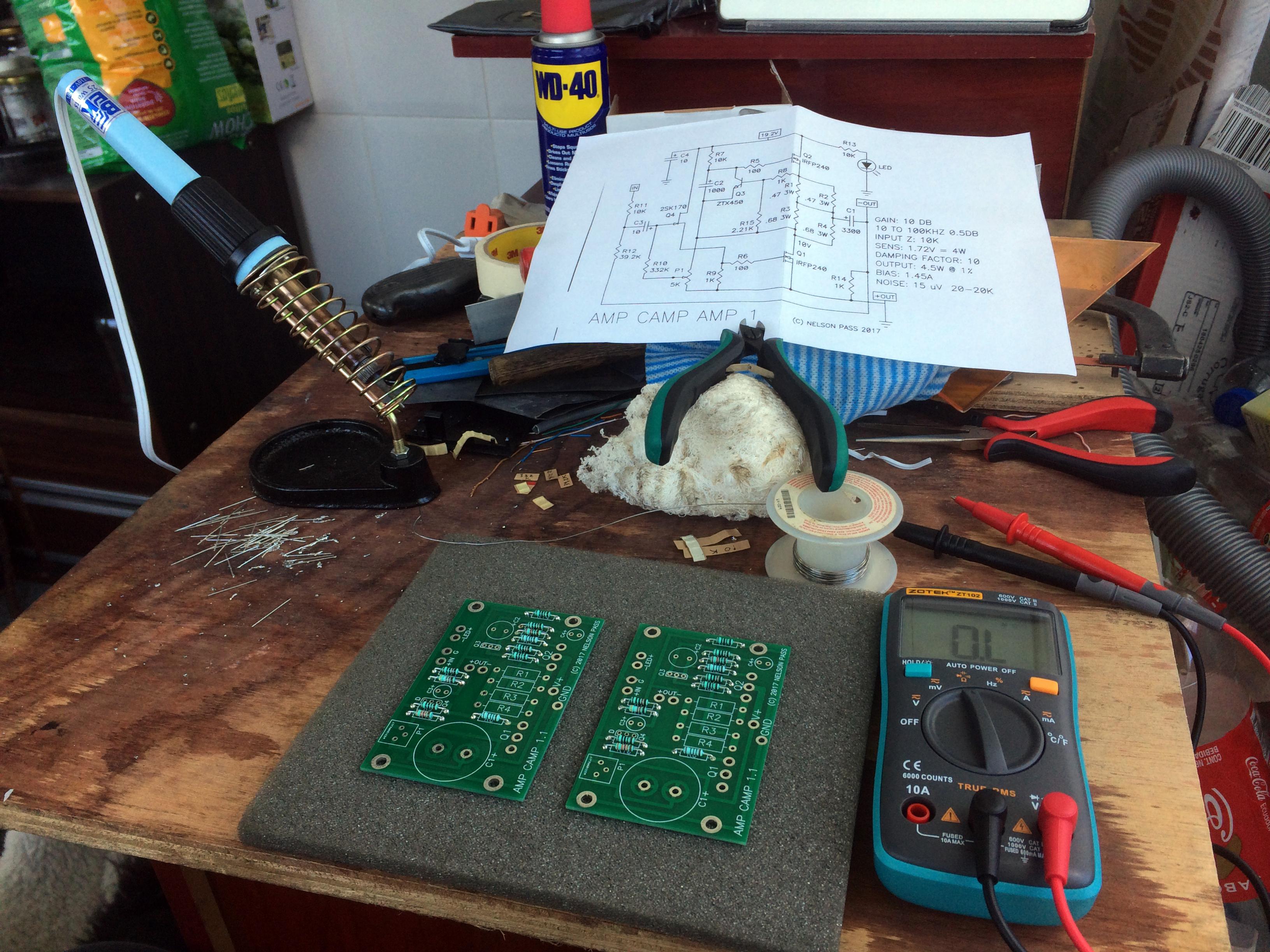
Amp Camp Amp - ACA
Amp Camp Amp - ACA
This looks great...look forward to incorporating one of these into whichever Vfet/SIT build presents itself.
I'll have 5 pcs of the Bulwark FE board underway to me next week.
If you would like 2 boards drop me an email, I'll either swap it for another one (preferred) or send them out for the cost of postage only worst case.
If you would like 2 boards drop me an email, I'll either swap it for another one (preferred) or send them out for the cost of postage only worst case.
So it looks like you'll either need to use an oscilloscope to measure frequency, or else design and build a little buffer + attenuator on your solderless breadboard, which drops the peak-to-peak voltage swing to 9V or less, without loading down the Marauder circuit too much. Then a standard multimeter on frequency counter mode MAY be able to see it's 50 kHz. Unfortunately the best way to debug this little breadboarded circuit, is with an oscilloscope.
You could try using a computer sound card and some spectrum analyser software. Note that proper sampling of a 50 kHz signal requires > 100 kHz sampling rate, which many modern sound cards will do. Even an older 44.1 kHz sound card might work, as it will show the "aliased" result of the 50 kHz signal at a lower frequency (5.9 kHz, I believe).
If you want to put a 36V peak to peak, 50 kHz square wave into your sound card, I won't try to stop you.
If you want to build a 36V-to-some-smaller-voltage attenuator, and install that between your Marauder and your sound card, I won't try to stop you. But I will mention that if you do have an attenuator, you might as well use your frequency counting DMM instead, since the DMM is smaller, more maneuverable, is battery powered so you don't need to connect either probe to "GROUND", and is cheaper (thus less expensive to replace if you accidentally blow it up).
If you want to build a 36V-to-some-smaller-voltage attenuator, and install that between your Marauder and your sound card, I won't try to stop you. But I will mention that if you do have an attenuator, you might as well use your frequency counting DMM instead, since the DMM is smaller, more maneuverable, is battery powered so you don't need to connect either probe to "GROUND", and is cheaper (thus less expensive to replace if you accidentally blow it up).
Sure, if you happen to have a reliable frequency counter that's what you're going to use. The soundcard idea was meant for those who do not have a frequency counter. A simple DC blocking cap and a voltage divider is all that it takes to check the frequency using a soundcard.
- Home
- Amplifiers
- Pass Labs
- Scourge, Bulwark, Marauder, Dreadnought "front end" cards for DIY VFET amp