
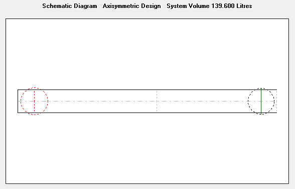
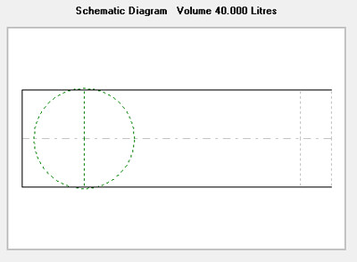
I have long thought about making a bandpass box with two transmission lines connected to the same driver. If I have understood it right, that is possible to model with Hornresp using the paraflex (PH1) configuration.
My goal is not to design anything for professional use but instead for my small living room. I am looking to make something that will dig low and hopefully also provide some punch in the mid-bass.
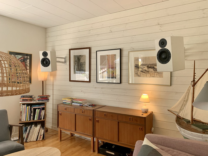
My living room is quite small and the back wall behind the speakers is 3,6x2,4 m. I want the sound to emanate from each corner 1/4 of the with and height of the room to suppress standing waves. In my room, there will be full corner loading up to about 100 Hz.
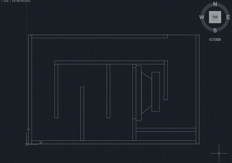
The form factor I then have chosen as constraints, as furniture blocks anything wider, is 60x94 cm as also the furniture is in the way �� If I had more space I could have made the mouth larger as I believe that is beneficial in many ways. Now I have to suffice with a ratio between the driver sd and area of the mouth of 1:1.
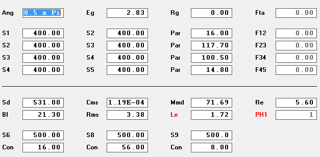
The driver I am using is the Eighteensound 12LW800.
May I ask, what are your thoughts on this? Could it be worth making some sawdust?
Last edited:
100 hz is not friendly here. But its okay, its manageable(or design a slightly longer HF section, larger csa in it or change the LF(but that already long, its ‘LF’).
Heres a potential helpful idea: and i do it now, regardless.
Leave a setup that allows for an adjustable exit to be sized for and attached with machine screwed flanged edge with gasket. Its anazing inside that box. Absolutely amazing. Double the fun but double the trouble. Its only ‘trouble’ if its a little bit here or there. Even then its onky excited in certain situations of pressure/velocity(if at all).
My testimony here is kinda funny, but grocery shopping or tools in the way of the mouth pointed otherwise directly at the back of my head were often actually plywood from home depot trips ended up fir the drive home. Always a little more bangbang and not any of ding A ling?!! Lol took awhile to actually notice the patern... im sliw..
Suddenly that became obvious. It was the most excellent oppo TUNE ity ever.
Now in PH mode i line up phase in both (with no actual exit to start) and then go for it at L45 Csa to play with and see how close any optional exit sizes
Might be handy even if assumed not needed.
David Mcbean really hooked us up here. Its so incredibly useful as a double qw pipe with large(harmonic lengths?) or small convenient( basket radiuses or multiples) as offset entries and everything that would be if they tap into eachother at a compound exit.
It might be useful to look at standing wave lengths instead of overall lengths (advanced centerline). Its very pronounced and can be wonderful it seems when they all mimic eachother and overall length is a bit of a wash if you are intersted in more than just a bottom end number here. I put together anither version of these with specific folds at a specific driver entry and it is a peach!!
Attachments

Last edited:
Regarding aperture area I believe it could work for moderate power levels but there could perhaps be a risk of turbulence at higher power levels, I'm not sure, seeing as this is a home setup it might be academic anyway, it may help to round of all sharp corners and edges in the area.
Based on my experience with both serial and parallel QW bandpass designs I would argue against this parallel Paraflex like 6th order.
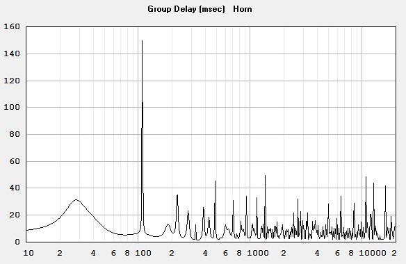
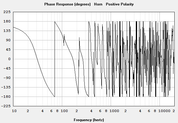
The notch in both spl, phase and GD graph is a sign of a cooperation problem of the two resonators. It might not seem like a big problem, but every QW parallel bandpass design I have heard to date does have a problem in the upper part of the pass band. You can avoid it by using a steep slope cross over and sufficiently low cross over point, but then there is very little need for this level of complexity.
Serial QW bandpass designs does have their own set of problems (or challenges as our politicians like to call them), but I find them much more well behaved in real life use.
Martinsson uses a 150 Hz cross over point for his ROAR15, and it does lend some "character" to the sound, it still sounds much better then the comparably smaller "glitch" on the upper part of the passband from the several Paraflex/TPCH designs we have built and tested.
Remember that the resonators will have different rate of change of tuning as a function of spl due to the nonlinear behavior of air at different pressures and aid particle velocities. This will exacerbate the problem greatly by making it a nonlinear pulsating flaw with the signal amplitude and frequency content.
I have pretty much abandoned the parallel QW designs for these exact reasons. I have tried several designs and never managed to work around this flaw. In my opinion the serial high order QW bandpass wins out in real life usage.
Listen to Martinssons ROAR15 and the HROAR in the BRL store in Gothenburg (which needs some DSP processing and a little damping in the front resonator to really sound good) for the sound quality attainable from high order serial QW bandpass.
One of the main advantages with serial QW bandpass designs is the ease of incorporating and using positive feedback to greatly increase the "virtual Bl" of the driver in the midbass region where it is most needed for great punch and vivid life like exuberant sound character.
Last edited:
Give it a whirl
Forsman ,
Don't let these guys shoot your idea down..... That little hiccup that you see just above 100hz (in this case) doesn't always exist in the real world, for example it didn't show up in measurements of the Paraflex Type "C" Classic or the Paraflex Type "R" 1x18 ..... In fact it doesn't show up in most of the Paraflex cabinets which have single rear paths ... It did however show up in some of our other builds but we have learned how to add damping material in the right place to solve the issue (if it does happen to appear within the cabinet's working range) ....So not a big deal really 😎 .... If necessary a good place to add a panel of open-cell foam would be at the turn in your High-Tuned QW resonator section . .
Your concept is solid .... We have had people working on Paraflex projects daily for a couple of years now so we know what to expect 🙂 .
Last edited:
Forsman,
How do you plan to mount the driver with that layout? Will there be a removable access hatch panel on the side of the cabinet where the driver is located?
How do you plan to mount the driver with that layout? Will there be a removable access hatch panel on the side of the cabinet where the driver is located?
What happened to the famous swedish masters of the 8th order pipe? Theyre getting older and not daring anymore? I think they need a beer or two and doctors orders: immediately have fun😀😀 again
Fwiw, stuff the rear chamber. Its in the latest update
Fwiw, stuff the rear chamber. Its in the latest update
Attachments
Last edited:
It was not my intention to be negative about this, I do not have sufficient hands on expirience with this type of layout to comment on its potential, my concern about the aperture area stems from that 1xSD in a tapped design, even with losses along the way, may not be sufficient to keep the velocity down below risk of turbulance when pushed, but as always I may be wrong about this.
No, youre totally right sir.
But the idea hovered around 12-15 m/sec and isnt a ‘build plan’ , rather instead its just a cushion of adjustment if needed so the idea to build these isnt so intimidating.
But the idea hovered around 12-15 m/sec and isnt a ‘build plan’ , rather instead its just a cushion of adjustment if needed so the idea to build these isnt so intimidating.
This is so Cool. I have read a lot from all of you in many threads and on FB. I am very grateful for your input. I just have to do some more hours of what’s called ”work” and then I’ll try to digest what’s been written.
Thanks! 🙂
Thanks! 🙂
My son had no prior knowledge about this discussion and this thread so I asked him a very open question.
"Can you describe and evaluate the pros and cons with the two TPCH we built with the two HROAR we built?
(TPCH is my prefered name for the paraflex layout with only straight non expanding sections - to easily differentiate them from the "normal" paraflexes with some (stepped) expansions)
He does like both a lot. Totally superior to any bass reflex, helmholtz based bandpass or closed boxes he has heard. He uses the two different TPCHs at a daily basis in his cars.
BUT.
He preferes the sound quality from the serial 8th order HROAR design. It sound more musical and "fun" with more "punch and vivid and organic effortless immediacy". Smoother and more even over their usable spectrum.
The TPCH is a brutal beast and I would not hesitate to recommend a Paraflex type box over a BR or Helmholtz based bandpass. But we both experience them to be a little "honky" and not as distinct and clean. There is always some small non-harmonic noise like overtone to bass coming from them.
The HROAR and ROAR does have their own easily recognizable character too, but I find it much easier to live with as it does not seem as "detached" from the original signal and as non-harmonic as from the TPCH.
True. I might have made a lot of mistakes and I might not have a clue what a true well designed Paraflex sounds like. But I quickly found these parallel QW bandpass boxes to be a dead end for me.
Paraflex seems like a great design though, and I can't disregard the enthusiasm in the high order QW facebook page. I would love to have a shootout between a Paraflex and a HROAR optimized for the same driver and the same car someday, but my ME/CFS gets in my way and precludes me from designing and building fun loudspeakers most of the time nowadays.
I'd like to chime in on the praise of the success Mathew and his crew has had (currently has) with the paraflex designs, they have managed to get an astonishing adoption globally in a very short time and with new designs and improvements on existing ones popping up like crazy.
I'm hoping to get to hear some of them in the future, and the way things are going it seems I will have no choice in the matter, they will be everywhere in few months 🙂
I'm hoping to get to hear some of them in the future, and the way things are going it seems I will have no choice in the matter, they will be everywhere in few months 🙂
True. I might have made a lot of mistakes and I might not have a clue what a true well designed Paraflex sounds like. But I quickly found these parallel QW bandpass boxes to be a dead end for me.
Me too in that it depends on the needs of the app with parallel BP = ~1.5 octaves max and series BP = ~2.5 octaves max.


A simple HROAR for your driver. It does not fit your size requirements, but I like the response (here in 0,5 Pi as per your original sim in your first post).
900 x 700 x 483 mm (21 mm plywood).
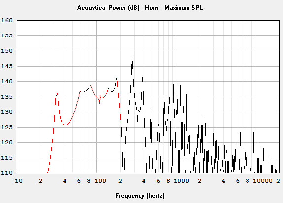
The nice mid bass peak centered around 85 Hz will definitely add a nice vivid, punchy and joyous character. It is also easy to EQ down to a flat response if you need to.
Last edited:


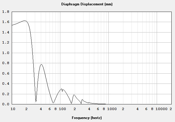
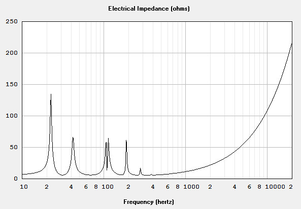
Here is the simulated response of the "original" PH1 Paraflex typ (green curve) with the HROAR12 (red curve).
I am concerned about the rapid shifts in the GD graph which indicate a cooperation problem between the two resonators. I guess (based on Matthew Morgan J comment) that you can minimize these problems with some careful application of damping within the resonators, but I would like to see some measurements at different spl levels before I rule out this problem as non existent or at least inconsequential for the intended application.
At the end of the day all there is to know is that all three of those men created something unique and very fun and exciting to experience. More importantly, if you take it, and mold it into your own excitement, interests, curiousity or motivation and hobby, then these guys haven't just created incredibly potent and powerful speaker designs. They've changed peoples lives or put something in it that is priceless. Not even they can appreciate what that is or how big it is.
How big it becomes... its a form of technical art to them, and science, and hard work. But its even MOAR then that... youll see what i mean, but you gotta go with your Ideas too. (Mix your ideas into this and you will appreciate it all and in a way thats probably the core value of the ‘human’ experience?
You owe it to yourself to listen and learn all this. Because when you do build it, in your own way, youll see exactly what im saying(beyond the silly typed words). Its exciting, its worth it. Do it, but do it in a way that honors your own ideas too 🙂
FWIW I think my 70 year old buddy, Karlson's K15 cabinet (development finished summer of 1951 - commercial debut fall 1952) owes its agility to its ~76 liter/110Hz center tuned front resonator . Even the little K12 w. Kappa 12A outpunches my FH1.
https://i.imgur.com/oRygnBt.png
https://i.imgur.com/oRygnBt.png
View attachment 941698
View attachment 941699
View attachment 941700
View attachment 941705
A simple HROAR for your driver. It does not fit your size requirements, but I like the response (here in 0,5 Pi as per your original sim in your first post).
900 x 700 x 483 mm (21 mm plywood).
The nice mid bass peak centered around 85 Hz will definitely add a nice vivid, punchy and joyous character. It is also easy to EQ down to a flat response if you need to.
So now its okay to put a mass loading on the exit? hroar)? That doesnt agree with Martinssons idea and its also whatever you might not find in your methods of analysis by that sim.
Stop demanding theres a better or worse. Ask someone whos not wanting to pick a favorite? Instead they just build so many and at random they run into the answer anyhow...
Theres 3 designs here.
Roar, paraflex and the other paraflex(motor entry outside if chamber.) the first and the last are a 90 degree turn away from each other and a subsequent distance as well .
The paraflex classic is 100 % able to kill them both on paper(sort of.....) and in difficult to make ‘perfect’. But its not parallel, or even was. Compound symbiotic? Sure, there's a name!? LOL, it kinda seems so? Stick a smart phone up inside and record while you listen or watch for whatever happens at specific frequencies.. use slow mo and use a powder or a particle? Not just a sweep.. one by one and with the idea that theres a null on the move..... cause it is and leaves sand dust trails to stick in moist surfaces right?? Yes!! Its been done and repeatedly. Its even easy, go play music all day at the ocean. Then look inside the next day at the salt and sand blasts left on the black gloss finish inside.
Its a great many things, but ‘shared space’ isnt parallel, if its up to a word to say ?? I don't really know what it is, its a swirling mess to try and navigate.. -and low pressure and scatter around low pressure zones and high velocities that drag across them but change is a tornado of marks in areas?? A dye would be awesome!
Last edited:
Thank you for all the valuable input.
Yes, I think I understand that the air in the pipe to some extent has a nonlinear behavior depending on variations in pressure in relation to the atmospherical pressure. I guess I have to test to see ;-)
The adjustable exit is an interesting idea. However, in this particular case, I have a rather small mouth so I´m not very inclined to restrict it even further. But I will remember it for future designs.Leave a setup that allows for an adjustable exit to be sized for and attached with machine screwed flanged edge with gasket
I have elaborated with most of the parameters you mention to get the notch as small as possible. Good to know that there are more ways of dealing with it.100 hz is not friendly here. But its okay, its manageable(or design a slightly longer HF section, larger csa in it or change the LF
cool, must try that.It might be useful to look at standing wave lengths instead of overall lengths (advanced centerline).
Good idea, I´ll round of all sharp edges.Regarding aperture area I believe it could work for moderate power levels but there could perhaps be a risk of turbulence at higher power levels, I'm not sure, seeing as this is a home setup it might be academic anyway, it may help to round of all sharp corners and edges in the area.
Interesting. You know I treasure your opinion. I might have to build two versions, one in series and one in parallel. I´m not saying that you are wrong, just that I think I need to hear for myself too.Based on my experience with both serial and parallel QW bandpass designs I would argue against this parallel Paraflex like 6th order.
The notch in both spl, phase and GD graph is a sign of a cooperation problem of the two resonators. It might not seem like a big problem, but every QW parallel bandpass design I have heard to date does have a problem in the upper part of the pass band. You can avoid it by using a steep slope cross over and sufficiently low cross over point, but then there is very little need for this level of complexity.
Serial QW bandpass designs does have their own set of problems (or challenges as our politicians like to call them), but I find them much more well behaved in real life use.
On the contrary, they are role models to me who I have learned tonnes from. But that does not mean that I won’t do the mistakes I’m being warned about. One important part of learning is to explore things that not all people believe are viable. I would regard ROAR and Paraflex designs to be just that ;-)Forsman , Don't let these guys shoot your idea down.....
Thats what I was hoping too. In the hight tuned pipe there is room to put in, or remove, thin sheets of plywood to try adjust the length of the pipe to minimize the notch.That little hiccup that you see just above 100hz (in this case) doesn't always exist in the real world, for example, it didn't show up in measurements of the Paraflex Type "C" Classic or the Paraflex Type "R" 1x18 .....
Haven’t thought of that..... If necessary a good place to add a panel of open-cell foam would be at the turn in your High-Tuned QW resonator section . .
Thanks, good to hear.Your concept is solid .... We have had people working on Paraflex projects daily for a couple of years now so we know what to expect 🙂 .
Either that or tigersaw… ;-)Forsman, How do you plan to mount the driver with that layout? Will there be a removable access hatch panel on the side of the cabinet where the driver is located?
That I have to explore. Haven´t used that function yet.Fwiw, stuff the rear chamber. Its in the latest update
Well, that puts things in perspective. Choosing between Paraflex and the in series configuration is more a choice of a different kind of good rather than a choice between good and bad.… He does like both a lot. Totally superior to any bass reflex, helmholtz based bandpass or closed boxes he has heard…
...The TPCH is a brutal beast and I would not hesitate to recommend a Paraflex type box over a BR or Helmholtz based bandpass. But we both experience them to be a little "honky" and not as distinct and clean. There is always some small non-harmonic noise like overtone to bass coming from them.
I agree, its really cool.I'd like to chime in on the praise of the success Mathew and his crew has had (currently has) with the paraflex designs, they have managed to get an astonishing adoption globally in a very short time and with new designs and improvements on existing ones popping up like crazy. 🙂
That is interesting that the bandpass has different sizes depending on the configuration.Me too in that it depends on the needs of the app with parallel BP = ~1.5 octaves max and series BP = ~2.5 octaves max.
Awesome, thanks. Now I might have to build three versions to test. My first suggestion in paralell, one in series and your HROAR design… I need a trip to the lumberyard 🙂View attachment 941698
A simple HROAR for your driver. It does not fit your size requirements, but I like the response (here in 0,5 Pi as per your original sim in your first post).
900 x 700 x 483 mm (21 mm plywood).
The nice mid bass peak centered around 85 Hz will definitely add a nice vivid, punchy and joyous character. It is also easy to EQ down to a flat response if you need to.
Great to see them overlayed.Here is the simulated response of the "original" PH1 Paraflex typ (green curve) with the HROAR12 (red curve).
I am concerned about the rapid shifts in the GD graph which indicate a cooperation problem between the two resonators. I guess (based on Matthew Morgan J comment) that you can minimize these problems with some careful application of damping within the resonators, but I would like to see some measurements at different spl levels before I rule out this problem as non existent or at least inconsequential for the intended application.
Yes, I think I understand that the air in the pipe to some extent has a nonlinear behavior depending on variations in pressure in relation to the atmospherical pressure. I guess I have to test to see ;-)
Well spoken Booger weldz. I only know you and Matthew from what you have written but I have had the opportunity to talk and discuss with both Martinsson and Circlomanen, on a Swedish forum and in person. I couldn’t agree more. As I wrote earlier, role models. I do not have the same depth of understanding when it comes to designing loudspeakers as you have. But that does not put me off from exploring it and following what makes sense to me. I believe that all of you who have created game-changing designs have walked against the mainstream to do so. I am very grateful for all your input, that you are taking your time to discuss and educate enthusiasts like me - thanks 🙂At the end of the day all there is to know is that all three of those men created something unique and very fun and exciting to experience. More importantly, if you take it, and mold it into your own excitement, interests, curiousity or motivation and hobby, then these guys haven't just created incredibly potent and powerful speaker designs. They've changed peoples lives or put something in it that is priceless. Not even they can appreciate what that is or how big it is.
How big it becomes... its a form of technical art to them, and science, and hard work. But its even MOAR then that... youll see what i mean, but you gotta go with your Ideas too. (Mix your ideas into this and you will appreciate it all and in a way thats probably the core value of the ‘human’ experience?
You owe it to yourself to listen and learn all this. Because when you do build it, in your own way, youll see exactly what im saying(beyond the silly typed words). Its exciting, its worth it. Do it, but do it in a way that honors your own ideas too 🙂
Last edited:
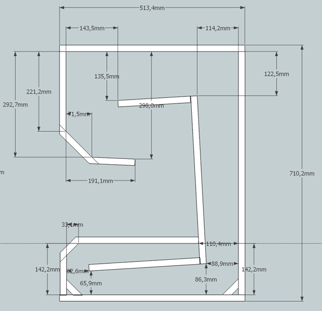
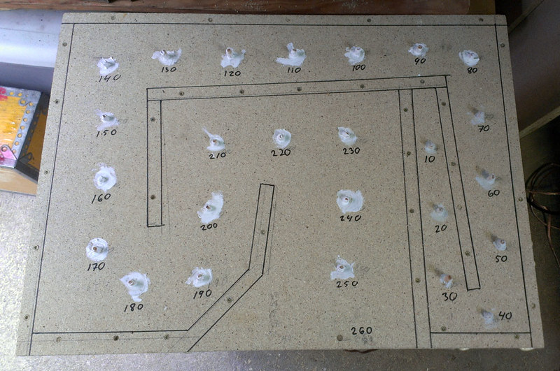
I actually did something along these lines of thought a few years ago. I did build a TH and measured SPL and phase in 10 cm increments all along the horn to find the high- and low-pressure spots. These spots I then used to experiment with damping to take out peaks, and constrictions to lift sag in the response curve. I also attached 2” waterpipes close to S2 as QW resonators to cancel out nasty peaks.Stick a smart phone up inside and record while you listen or watch for whatever happens at specific frequencies.. use slow mo and use a powder or a particle? Not just a sweep.. one by one and with the idea that theres a null on the move..... cause it is and leaves sand dust trails to stick in moist surfaces right?? Yes!! Its been done and repeatedly. Its even easy, go play music all day at the ocean. Then look inside the next day at the salt and sand blasts left on the black gloss finish inside.
Its a great many things, but ‘shared space’ isnt parallel, if its up to a word to say ?? I don't really know what it is, its a swirling mess to try and navigate.. -and low pressure and scatter around low pressure zones and high velocities that drag across them but change is a tornado of marks in areas?? A dye would be awesome!
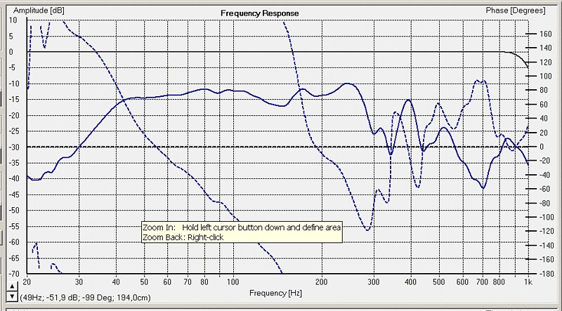
If someone is interested in the measurements they can be downloaded here 🙂
Last edited:
- Home
- Loudspeakers
- Subwoofers
- TLBP6 - Paraflex