Chris, the UTC2050V amp your brother tested was not a composite version? Thanks for involving your brother as a second opinion to your own. When you talk about "sound-stage", I am lost.
hi FF
yes the UTC2050V was the normal ebay kit board. i only want to point to the resistor between pin 1+2.
in this case: with sound stage i mean the places where the singer or instruments are located. this gets mixed if the amp sound not good. sometimes i use the name sound stage for deepness or width. sorry this is confusing i should be more precise in future.
the amp sounds like he want just to through out the voices and instruments out. it feels that all singer and instruments to not play together.
chris
Hi Chris, when "it feels that all singers and instruments do not play together" it should be good for fusion jazz. I always have the feeling that a number of musicians play each their melody.
Anyway, an outer regulation loop (composite) may bring the ensemble back together such that also your brother is convinced.
Many thanks for the good explanation from someone who really knows how to appreciate sound quality.
Anyway, an outer regulation loop (composite) may bring the ensemble back together such that also your brother is convinced.
Many thanks for the good explanation from someone who really knows how to appreciate sound quality.
Thank you chris that's helpful. but please try to avoid the 510 resistor at pin 1 +2.
Hi Chris.
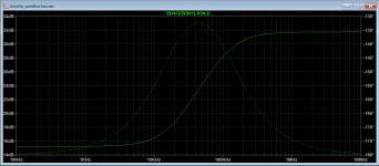
Keeping the right value of resistor between input AND with resistor between in+ and GND is mandatory to keep TDA stable with a signal gain lower than recommended 24 or 30dB. Beyond this theoric answer, I 've made some test with and serial RC network between inputs rather than a resistor. This allows to keep low noise gain at DC and LF but to have a sufficient one at HF where phase margin getting too low and amp tend to oscillate.
With R=510Ω and C=2.7nF, I get permanent oscillation (not only close to clipping) at 28kHz where noise gain close to 20dB. See noise gain plot attached.
IMHO this confirm the need to use the right noise gain, then I decided to stick with safe value : 510Ω.
Chris
Attachments
Last edited:
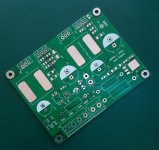
I appreciate very much that you spend time on this LM1875 design. Not a lot of practical experience is available until now. You are the first with a really nice PCB layout.
Hello,
Thanks for your words and also thanks to remind me those order of magnitude related to the capabilities of my acquisition chain....94 is not 130 !. 94dB is 16bit ENOB wich is already very good at least for diyers !
Even if the current smps is cause of some unexpected defaults of the signal, this is not the main cause with lead to not so good THD figures : I have tried a linear supply and got the same the distortion profile : odd and even harmonics and values within 10db from H2 to H8 (8Ω, -3dB).
I have some leads to pursue in order to improve results :
- do not connect scope while measuring : it has a visible impact to noise floor (ground loop)
- use a laptop battery powered for arta and focusrite
- try different ground connection for amp/focuriste output / focusrite input
- try a pcb mod related to TDA2050 decoupling
Chris
Hi AIM65
i am not the expert in composite amp.
I have just in mind :
- the comment about the resistor at pin 1+2 from Mark as I wrote.
- if I tested the UTC 2050 chip i got an oscillation as i use the 100pF cap as Cf like with the LM1875 - this was not good- Hugh oscillation then i start to us different Cf caps to look at 80khz square
https://www.diyaudio.com/forums/chip-amps/341675-ebay-mono-lm1875-kit-60.html#post6131748...then FF give me the hint to use the resistor between pin 1+2.
for me the LM1875 are really different chip
1875 is good for 8R because of max voltage about +/-30V...at 4R you are out of SOA - thump on/off🙄 Cf can be 100pF milar
UTC less power at 8R because of max supply +/-25V but stronger at 4R. so i use what rabbitz wrote --> transformer with 15VAC to get about 21,5VDC at the amps. UTC has no thump🙂, CF max 10pF
i am really happy that you take your time an "restart" this project..Thank you very much !!
chris
Thank you chris that's helpful. but please try to avoid the 510 resistor at pin 1 +2.
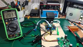
I took time to provide you a real answer, I made the test by removing resistor between inputs. Result: it oscillate, see picture where probe is 1:1 connected at the output and with input open.
Regarding your previous message and Mark comment :
He’s right, but in our very particular case we do not raise noise gain too much: we just raise it to its nominal value given by manufacturer, so nothing wrong with that.
In usual inverting or non-inverting configurations, TDA2050 is stable with a gain of 30dB minimum. In those configurations noise gain is equal to signal gain.
Within our composite amp, signal gain is lowered to a value where amp is unstable (4.8 on my amp), in order to get amp stable, noise gain is modified by R19 and R20 (not R19 alone) which set a noise gain of 38.7 (32dB) where amp is stable. Amp stability criteria apply on noise gain, not signal gain, but usually those two values are the same.
While Googling to get some education on the subject, I found 3 uses cases of this noise gain trick on opamp:
• Stabilize decompensated opamp
• Stabilize amp with too large capacitive load
• Magnify internal defect of opamp (such as noise or distortion) in order to qualify them
4th use case in our one: stabilize an amp part of a larger control loop.• Stabilize amp with too large capacitive load
• Magnify internal defect of opamp (such as noise or distortion) in order to qualify them
Chris
Attachments

done some tests yesterday and found that I had a bad gnd connection for the input of the focusrite as it was connected to the gnd point of the load. Now focusrite output, focusrite input and amp signal gnd are all connected to the same signal gnd of the pcb...much better 🙂.I have some leads to pursue in order to improve results :
Chris
- do not connect scope while measuring : it has a visible impact to noise floor (ground loop)
- use a laptop battery powered for arta and focusrite
- try different ground connection for amp/focuriste output / focusrite input
- try a pcb mod related to TDA2050 decoupling
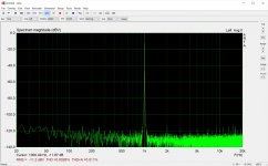
I also install new selfs and a new mosfet on the supply. This has a positive impact on THD+N, as those selfs doesn't go into core saturation. But this supply is still too small, V2 is still awaited. For V2, I've received today the pcb.
Some measurements :
Pic#1 : 8R / max power before clipping start
Pic#1 : 8R / 2.82V=1W
Chris
Attachments

Wow, that´s some lovely results! Congrats!
Still can´t get over how cool that power supply is.
WHen I look at it though something in me says it can´t work.
Did you investigate into other switching regulators that do 5A or more?
I might check out the LTC3780 which is buck&boost.
Still can´t get over how cool that power supply is.
WHen I look at it though something in me says it can´t work.
Did you investigate into other switching regulators that do 5A or more?
I might check out the LTC3780 which is buck&boost.
LTC3780 is a controller : it requires external MOSFET, two as it's synchronous. It's much more complex and the design goal of this project is to build a composite amp, not a psu, ... even if good psu is mandatory 🙂
My Version 2 supply, which is ongoing, is built around an XL4016, which is 5pin and has on chip PMOS switch, 12A rated... With a 10A rated self, I expect it to be much more well suited to the little amp. But for now, it's too early to speak of results, as I haven't built it yet : I'm still waiting for parts from LCSC.
Version 1, built round LM2596 is not enough...at least of negative side.
Chris
Last edited:
Hi all!
And sorry to everyone for me being away for a long time from here!
I built this you see...
I can see I have now a serious task reading all the findings in this thread people have made!
Firstly, congrats to AIM65 for the new proto. Looks promising.
Just a quick comment about the ARTA measurements though:
You need to make all your measurements at the same dBV level, othervice you need several loopback THDs of your system with different input levels.
You need to make an attenuator so that every measurement has the same dBV level, which must be the same as your system loopback measurement was made at.
0dBV that is...
Then the rest is pure mathematics.
Thanks for the hint. That looks like a promising candidate and I agree that an integrated switch makes life/PCB-layout at least a little easier.My Version 2 supply, which is ongoing, is built around an XL4016
LTC3780 would make a nice generic "power block" as it is buck&boost and could be used for a number of amps.
A transfomer+buck/boost-converter is still simpler than a AC/DC-SMPS.
I personally would like a regulated PSU as it doesn´t suffer from sagging rail voltages like a linear PSU.
There are ready-made modules on eehbay and amasin (XL4015/XL4016/LTC3780) just like the LM2596 which I have a few of.
Cheap as chips but apparently the LTC3780-ones are more expensive and don´t seem very well built.
I might give the XL4016 a try and yes, please report your findings about the design.
Hi all!
And sorry to everyone for me being away for a long time from here!
I built this you see...
....[/QUOT
Hi palstanturhin
Nice that you build an amp but the pic is too small to look at.
chris
@AIM65, The THD values go in the right direction  .
.
If your Scarlett 2i2 has 0.002% THD+N on the DAC and another 0.002% THD+N on the ADC, it seems to me that with the last values you measure you are approaching the limits of your system.
.If your Scarlett 2i2 has 0.002% THD+N on the DAC and another 0.002% THD+N on the ADC, it seems to me that with the last values you measure you are approaching the limits of your system.
@palstanturhin, Really good to see you back  . We always miss you when you are gone for longer periods. But, we also know that Finland is very cold during the winter and that you probably use winter-sleep, like the polar-bears do, for the Finnish population. Spring is here and you are as born anew.
. We always miss you when you are gone for longer periods. But, we also know that Finland is very cold during the winter and that you probably use winter-sleep, like the polar-bears do, for the Finnish population. Spring is here and you are as born anew. Hi palstanturhin
Nice that you build an amp but the pic is too small to look at.
chris
Oops, lets retry...
Its a DAC...
- Home
- Amplifiers
- Chip Amps
- LM1875 in parallel configuration and used in a composite amplifier.